Current collector for double electric layer electrochemical capacitors and method of manufacture thereof

a current collector and electrochemical capacitor technology, applied in the field of electrochemical supercapacitors, can solve the problems of low stability, low specific resistance of thin oxidation layer, low operating stability, etc., and achieve high over-voltage of hydrogen and oxygen gassing, low cost, and convenient availability

Inactive Publication Date: 2006-12-28
UNIVERSAL SUPERCAPACITORS LLC
View PDF99 Cites 53 Cited by
  • Summary
  • Abstract
  • Description
  • Claims
  • Application Information

AI Technical Summary

Benefits of technology

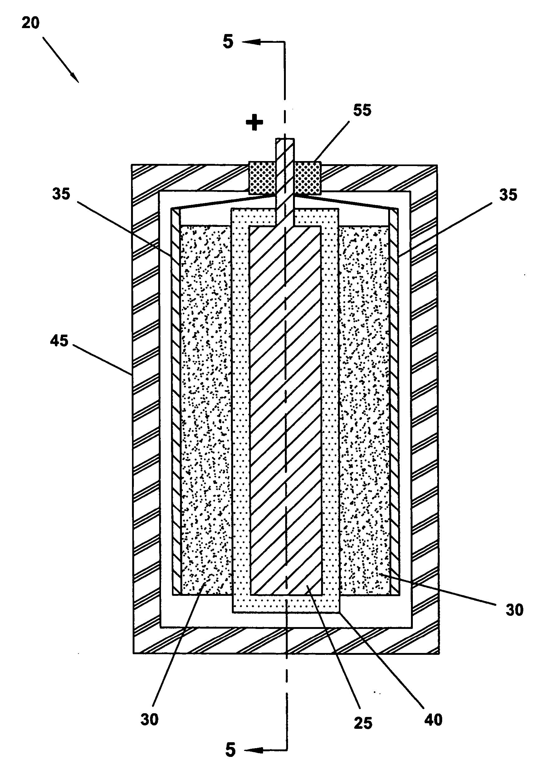
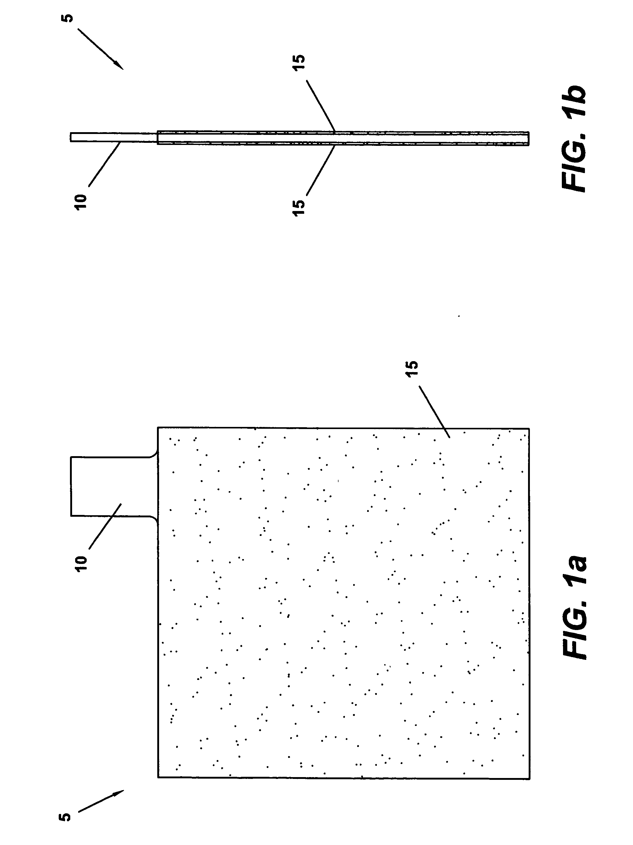
[0014] A current collector of the present invention is designed in view of the aforementioned requirements and concerns. For example, it is understood that the material used to construct a current collector can affect various capacitor parameters, such as: maximum operating voltage; operating temperature; operating stability; the range of electrolytes that can be used; service life; and cost. Based on the foregoing limitations, including the variety of differ

Problems solved by technology

However, it has also been determined that after extended operation of such DEL capacitors, a thin oxidation layer with high specific resistance and low stability will be formed by a r

Method used


Image

  • Current collector for double electric layer electrochemical capacitors and method of manufacture thereof
  • Current collector for double electric layer electrochemical capacitors and method of manufacture thereof
  • Current collector for double electric layer electrochemical capacitors and method of manufacture thereof

Examples


example 1

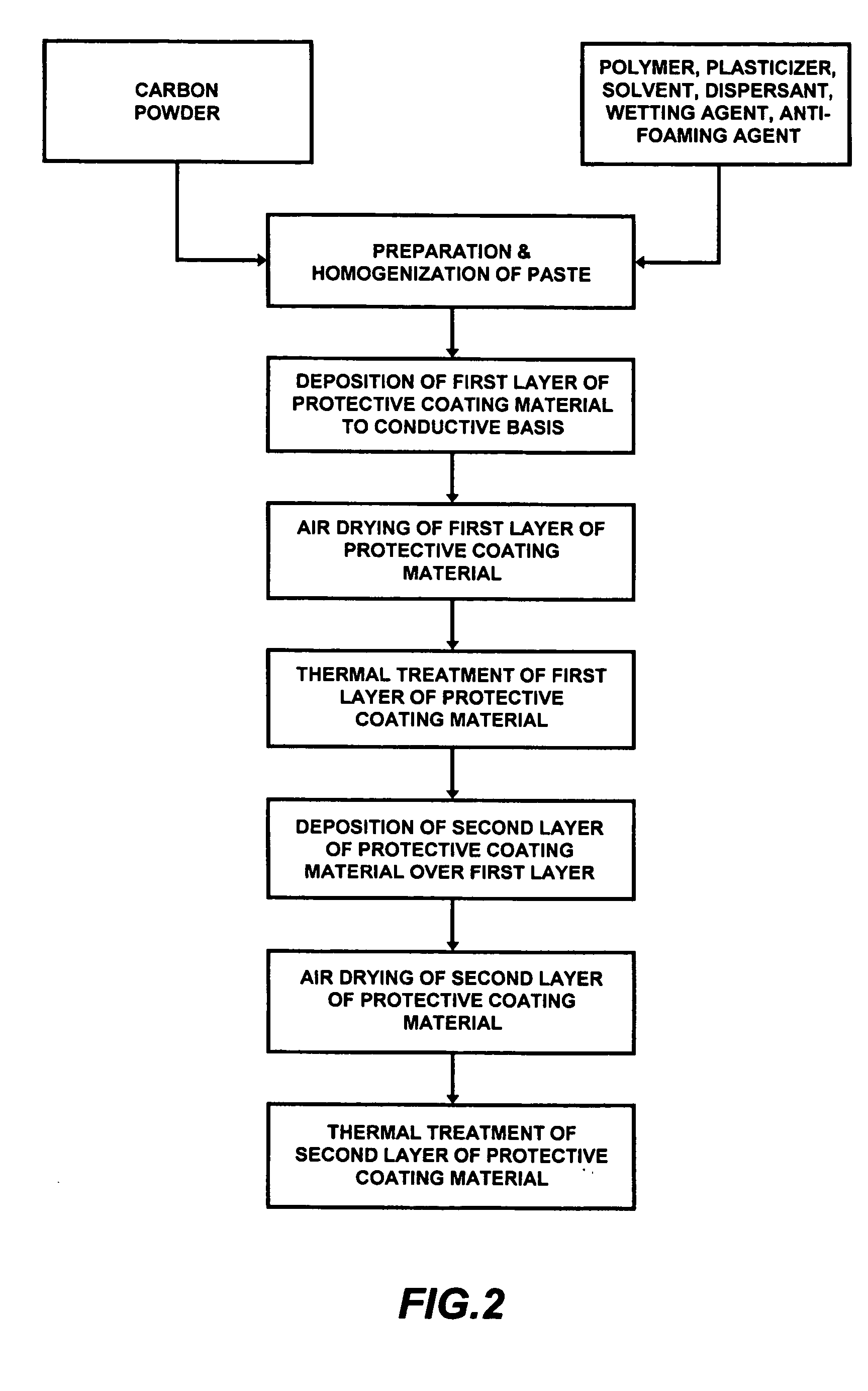
[0048] An exemplary current collector was manufactured according to the technique described above. The current collector had conductive basis dimensions of approximately 135×72×0.2 (mm). A protective coating material was deposited to the conductive basis in two separate layers, such that the final protective layer thickness was approximately 50 μm. The conductive basis was manufactured from a lead alloy, namely an alloy comprised of approximately 97% lead and approximately 3% tin. The composition of the current collector protective coating paste was approximately 6.0 weight % carbon powder; 5.2 weight % perchlorovinyl polymer; 8.2 weight % plasticizer; 80 weight % solvent (acetone, n-butyl acetate, toluol); 0.3 weight % dispersant; 0.15 weight % wetting agent (surfactant); and 0.15 weight % antifoaming agent. After thermal treatment of the second of the two protective coating material layers, the composition of the protective layer was 30 weight % carbon powder; 45 weight % perchlor...

example 2

[0069] Another exemplary current collector was manufactured in a manner similar to that described above. The current collector again had conductive basis dimensions of approximately 135×72×0.2(mm). A protective coating material was deposited to the conductive basis in two separate layers, such that the final protective layer thickness was approximately 50 μm. The conductive basis was manufactured from a lead alloy, namely an alloy comprised of approximately 99% lead and approximately 1% tin. The composition of the current collector protective coating paste was approximately 4.0 weight % carbon powder; 9.7 weight % perchlorovinyl polymer; 6.0 weight % plasticizer; 80 weight % solvent (acetone, n-butyl acetate, toluol); 0.1 weight % dispersant; 0.1 weight % wetting agent (surfactant); and 0.1 weight % antifoaming agent. After thermal treatment of the second of the two protective coating material layers, the composition of the protective layer was 20 weight % carbon powder; 52 weight %...


PUM

PropertyMeasurementUnit
Timeaaaaaaaaaa
Thicknessaaaaaaaaaa
Temperatureaaaaaaaaaa

Abstract

A current collector for use in a capacitor having an aqueous or non-aqueous electrolyte, such as an aqueous sulfuric acid electrolyte. The conductive basis of the current collector may be manufactured from a number of conductive metals but, preferably, is comprised of lead or a lead alloy. The portion of the conductive basis that will be in contact with the electrolyte is provided with a protective layer that is created by deposition of one or more layers of one or more protective coating materials thereto. Each protective coating material is comprised of at least a conductive carbon powder and a polymer binder that is resistant to the electrolyte. Preferably, but not essentially, the protective coating material(s) are applied to the conductive basis in the form of a paste, which is subsequently subjected to a solvent evaporation step and a thermal treatment step. The resulting protective layer is also substantially devoid of pores through which the electrolyte can permeate.

Description

[0001] This application claims the benefit of PCT application Ser. No. PCT / RU05 / 000349, filed on Jun. 24, 2005.BACKGROUND OF THE INVENTION [0002] The present invention is directed to the field of electrochemical capacitors, and particularly electrochemical supercapacitors. More specifically, the present invention is directed to a current collector for use in a double electric layer electrochemical supercapacitor electrode assembly. [0003] There is an increasing focus on the use of capacitors as a means for storing electrical energy. These capacitors can efficiently store and redistribute a large amount of electrical energy. For example, such capacitors may be used: as a main power supply; as a back-up power supply; and for power quality assurance (e.g., to compensate for short-term power “surges”, “spikes”, and “skips” common to utility-supplied electric power). Such capacitors may also be used to provide load-leveling by storing an amount of electrical energy provided during off-pe...

Claims


Application Information

Patent Timeline
IPC IPC(8): B32B15/04B05D5/12
CPCH01G9/048Y02E60/13Y10T29/417H01G11/58H01G11/22H01G11/68Y10T428/31678
Inventor KAZARYAN, SAMVEL AVAKOVICHNEDOSHIVIN, VALERY PAVLOVICHKAZAROV, VLADIMIR ALEXANDROVICHKHARISOV, GAMIR GALIEVICHLITVINENKO, SERGEY VITALIEVICHRAZUMOV, SERGEY NIKOLAEVICH
Owner UNIVERSAL SUPERCAPACITORS LLC
Why Eureka
Try Eureka