Shield cable, manufacturing method of the shield cable, and wireless communication module

Inactive Publication Date: 2014-01-02
CANON COMPONENTS INC
View PDF5 Cites 7 Cited by
  • Summary
  • Abstract
  • Description
  • Claims
  • Application Information

AI Technical Summary

Benefits of technology

[0011]To improve the shielding capability of the strip line cable disclosed in Patent Document 2, an outer conductor of the cable is formed by additionally applying a conductive paste or attaching a metal foil to a side wall between front and back surfaces on which GND conductors are disposed, thereby covering the entire cable by an insulating film. The adhesiveness between the added conductor and the side surface is low in the cable, and the bondability between the GND conductors and the added conductor is low. Therefore, the outer conductor may be

Problems solved by technology

When the coaxial cable disclosed in Patent Document 1 is used for a transmission line of a wireless communication module in which the reduction in the dimension and thickness is demanded, it is difficult to reduce the space, because the coaxial cable has a limit in bending at a small radius of curvature.
This leads to an

Method used


Image

  • Shield cable, manufacturing method of the shield cable, and wireless communication module
  • Shield cable, manufacturing method of the shield cable, and wireless communication module
  • Shield cable, manufacturing method of the shield cable, and wireless communication module

Examples


Example

First Embodiment

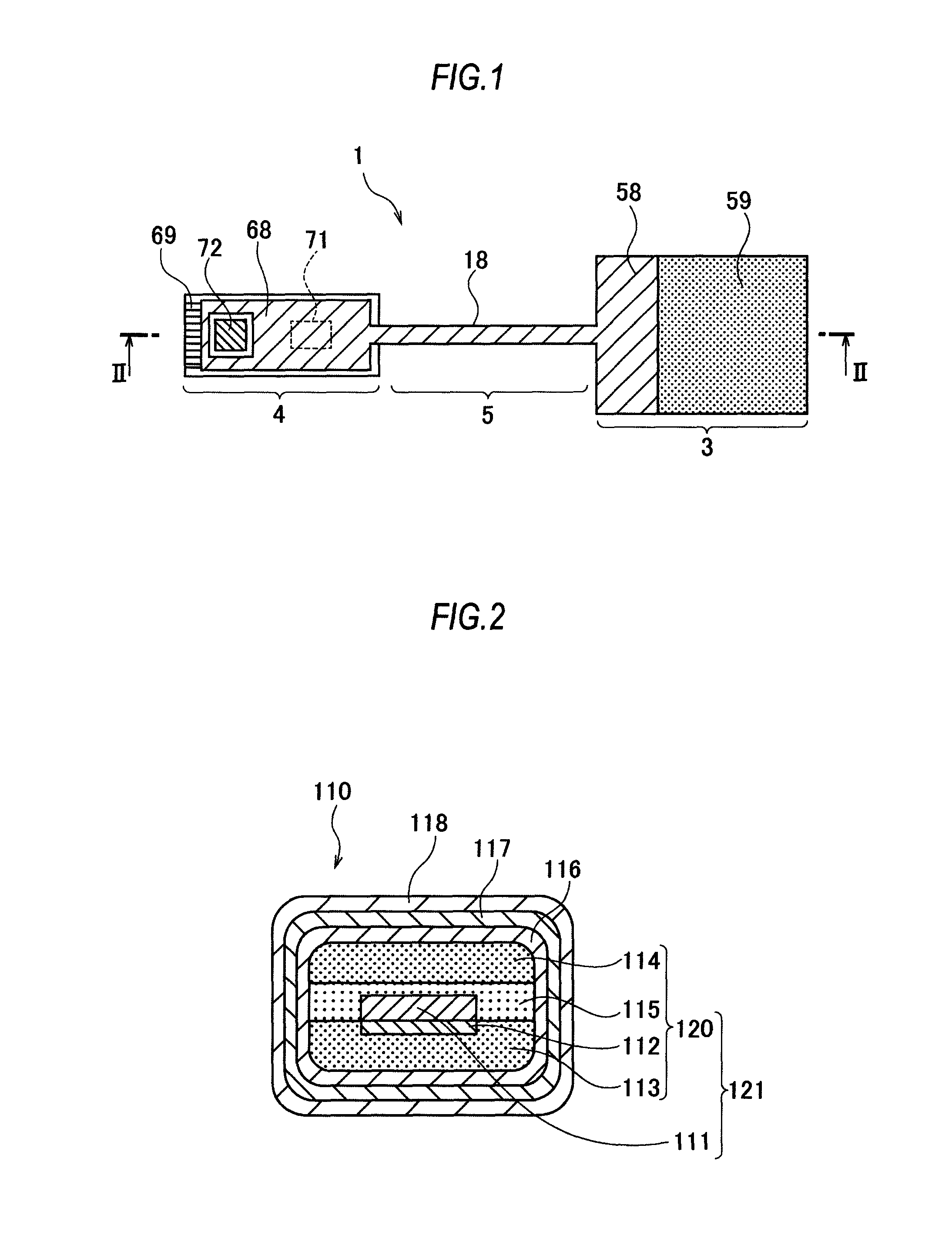
[0064]A structure and a manufacturing method of a shield cable 110 according to the first embodiment will be described with reference to FIGS. 2 and 3. FIG. 2 is a sectional view of the shield cable 110 cut in a direction orthogonal to a longitudinal direction. In the shield cable 110, a center conductor 111 formed by copper foil is surrounded by an internal dielectric 120, an outer easy-adhesion layer 116 formed by surface treatment is positioned around the internal dielectric 120, an outer conductor 117 formed as a shield is positioned around the easy-adhesion layer 116, and a protection film 118 further covers around the outer conductor 117.

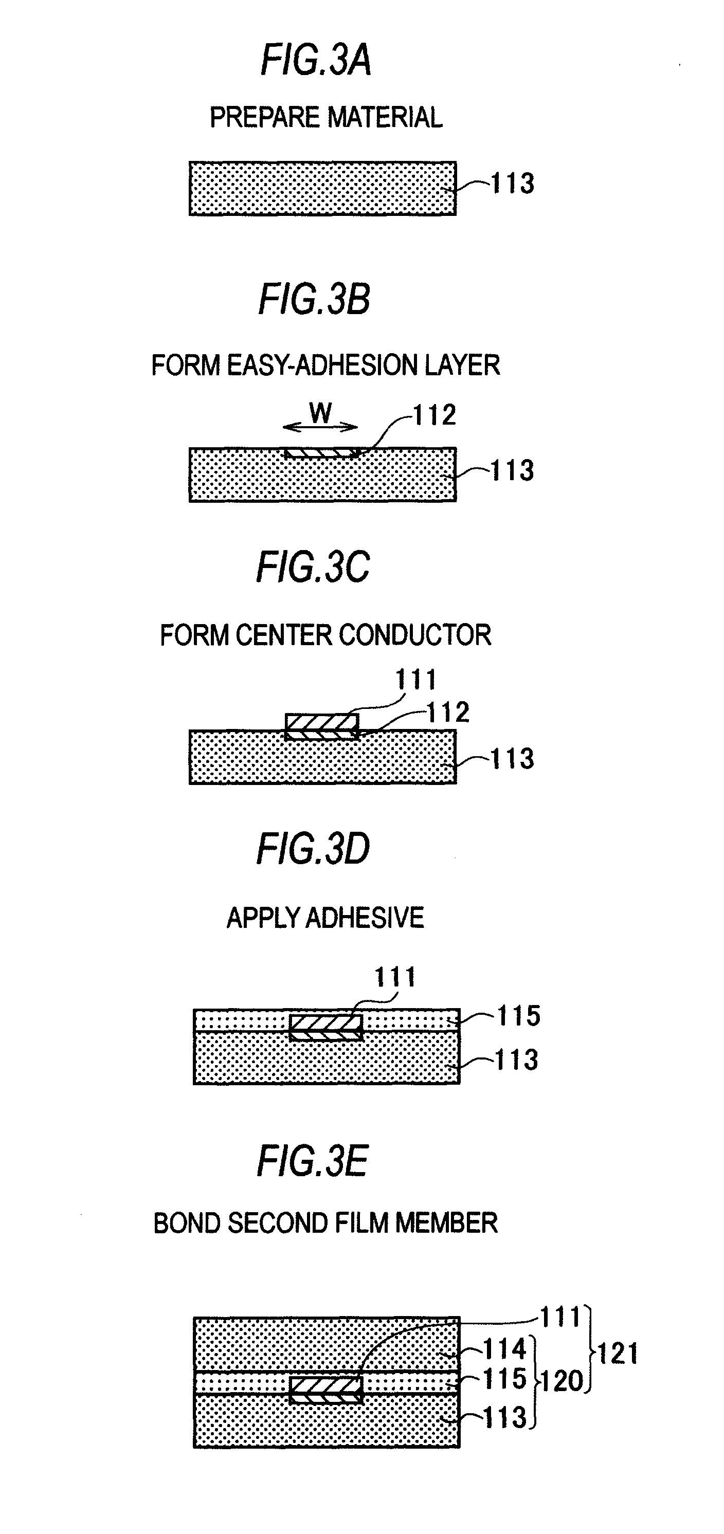
[0065]The manufacturing method of the shield cable 110 will be described with reference to FIGS. 3A to 3I. FIGS. 3A to 3I are views illustrating a series of manufacturing steps of the shield cable 110.

[0066](1-A) A polyimide film that is an insulating resin in an A4 size with a thickness of 25 μm is prepared as a first film mem...

Example

Second Embodiment

[0079]A structure and a manufacturing method of a shield cable 210 according to the second embodiment will be described with reference to FIG. 4A to 4I.

[0080]FIGS. 4A to 4I are views illustrating a series of manufacturing steps of the shield cable 210.

[0081](2-A) A cyclo-olefin polymer film (hereinafter, called “COP film”) that is an insulating resin in an A4 size with a thickness of 50 μm is prepared as a first film member 213 (FIG. 4A).

[0082](2-B) A nickel exposure mask with a plurality of openings in a shape of the center conductor (mask with a plurality of openings with a width of 90 μm and a length of 200 mm) is closely attached to one of the surfaces of the first film member 213, and UV light is applied for 3 minutes by a low-pressure mercury lamp to form an easy-adhesion layer 212 (FIG. 4B). A method similar to a method disclosed in Japanese Laid-open Patent Publication No. 2008-94923 can be used in this step.

[0083](2-C) A center conductor 211 is formed by ap...

Example

Third Embodiment

[0093]A structure and a manufacturing method of the shield cable 310 according to the third embodiment will be described with reference to FIG. 5A to 5I. FIGS. 5A to 5I are views illustrating a series of manufacturing steps of the shield cable 310. The manufacturing step in the present embodiment can be more simplified than the manufacturing step of the shield cable 210 in the second embodiment, and the number of types of material can be reduced.

[0094](3-A) A cyclo-olefin polymer film (hereinafter, called “COP film 313”) that is an insulating resin with a thickness of 50 μm is prepared (FIG. 5A). In the present embodiment, the size of the COP film 313 is reserved so that one side in the width direction (right side in FIG. 5A) from the position for forming a center conductor 311 is larger.

[0095](3-B) An easy-adhesion layer 312 is formed on one of the surfaces of the COP film 313 (FIG. 5B). This step is similar to the step (2-B) of the second embodiment.

[0096](3-C) The...


PUM

PropertyMeasurementUnit
Thicknessaaaaaaaaaa
Thicknessaaaaaaaaaa
Electrical resistanceaaaaaaaaaa

Abstract

A shield cable includes: a first film member made of an insulating resin; a second film member made of an insulating resin; a laminated body including a center conductor surrounded by the first film member and the second film member; an easy-adhesion layer positioned around the laminated body; an outer conductor positioned around the easy-adhesion layer; and a protective film that covers around the outer conductor, wherein the shield cable is flat when viewed in cross section.

Description

CROSS-REFERENCE TO RELATED APPLICATIONS[0001]This application is based upon and claims the benefit of priority of the prior Japanese Patent Application No. 2012-147334, filed on Jun. 29, 2012, the entire contents of which are incorporated herein by reference.BACKGROUND OF THE INVENTION[0002]1. Field of the Invention[0003]The present invention relates to a shield cable used in a transmission line unit of a high frequency signal, a manufacturing method of the shield cable, and a wireless communication module using the shield cable that can be mounted on a communication device.[0004]2. Description of the Related Art[0005]In recent years, reduction in dimension and thickness is demanded in wireless communication modules mainly used for communication devices, such as mobile phones, digital cameras, printers, and other mobile devices, and accurate arrangement in the housings of the communication devices is also demanded. Therefore, not only satisfaction of electromagnetic specifications, ...

Claims


Application Information

Patent Timeline
IPC IPC(8): H01B11/00H01Q1/48H01B13/22H01Q1/50
CPCH01B11/00H01Q1/50H01Q1/48H01B13/22H01P3/06H01P3/085H05K1/0219H05K1/189H05K3/284H05K2201/0715Y10T29/49117
Inventor KANOME, OSAMUMIZUNO, HIRONOBUHATTORI, YOSHIHIRO
Owner CANON COMPONENTS INC
Why Eureka
Try Eureka