Diaphragm pump for fluid

A technology for diaphragm pumps and fluids, which is applied to parts, pumps, and pump components of pumping devices for elastic fluids, and can solve the problems of high probability of loss or damage, easy failure reliability, and difficulty in miniaturization of diaphragm pumps, etc. problems, to achieve easy and rapid manufacturing, reduce manufacturing workload, and reduce the number of parts

Inactive Publication Date: 2014-06-04
DATA PLASTIC INDAL
View PDF4 Cites 0 Cited by
  • Summary
  • Abstract
  • Description
  • Claims
  • Application Information

AI Technical Summary

Problems solved by technology

[0004] However, if the umbrella-shaped valve core is used, there are problems in that the number of parts increases, the assembly operation takes time, and the probability of loss or damage during operation is high.
There is also the problem that the manufacturing cost becomes high
In addition, there is a problem that in order to prevent interference between the diaphragm and the umbrella-shaped valve element in the pump chamber, the pump chamber needs to be enlarged, and it is difficult to reduce the size of the diaphragm pump as a whole.
In addition, there are the following problems, that is, by using a small number of umbrella-shaped valve cores, it is easy to cause failure or the reliability of operation is low; noise during opening and closing operation

Method used


Image

  • Diaphragm pump for fluid
  • Diaphragm pump for fluid
  • Diaphragm pump for fluid

Examples


Embodiment Construction

[0037] Hereinafter, the present invention will be described in detail based on the illustrated embodiments.

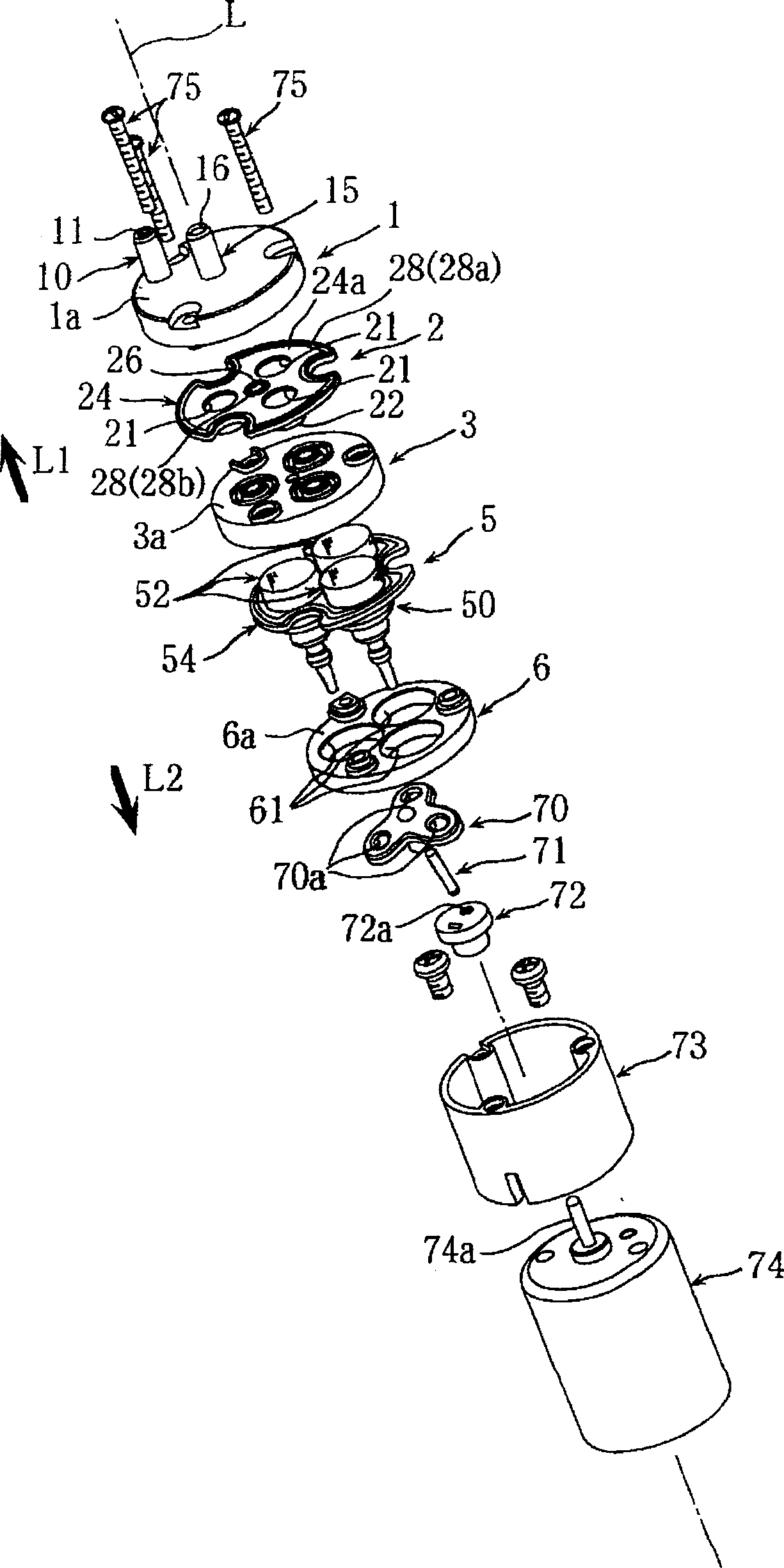
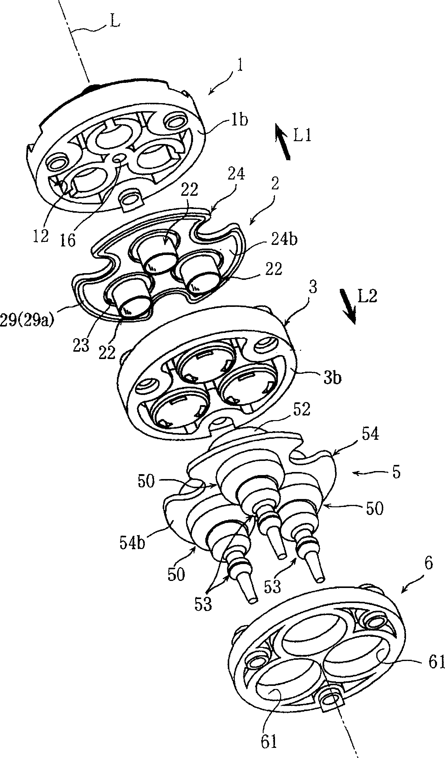
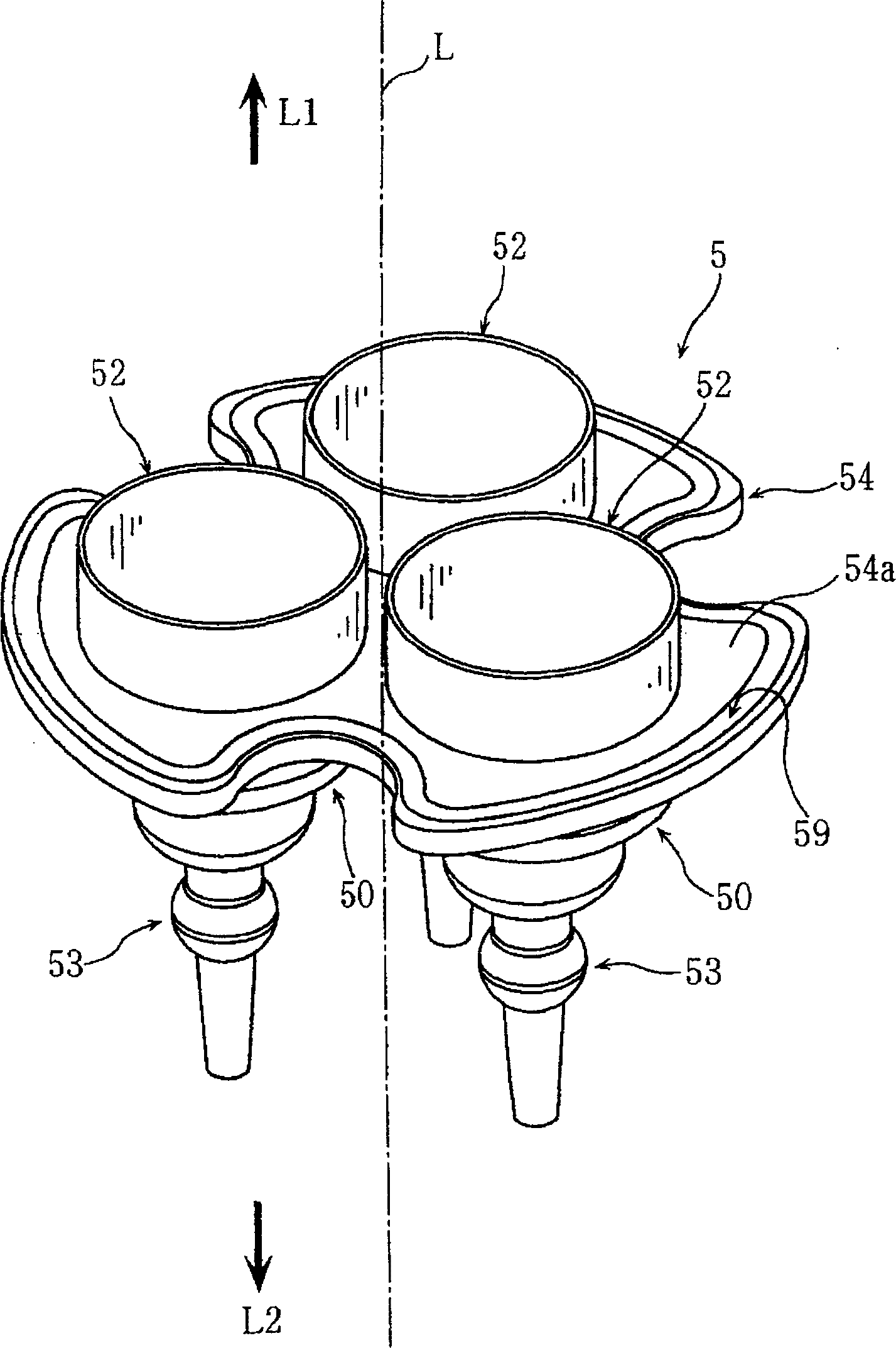
[0038] exist figure 1 and figure 2 Among them, the fluid diaphragm pump of the present invention has: a cover 1 having a small cylindrical suction port 10 and a discharge port 15 protruding in one direction L1 of the axis; The suction valve membrane assembly 2 of the short cylindrical suction valve membrane 22; the diaphragm assembly 5 with three bowl-shaped diaphragms 50 opening to the axial direction L1; installed between the suction valve membrane assembly 2 and the diaphragm assembly 5 The middle cover body 3; the holding member (support member) 6 that contacts and supports the diaphragm assembly 5 from the other axis direction L2 side.

[0039] In addition, in the present invention, the central axis of the entire diaphragm pump for fluid is referred to as the axis L. In addition, the arrow L1 direction side along the axis L is referred to as an axis-one direct...


PUM


Abstract

PURPOSE: A diaphragm pump for fluid is provided to reduce the overall length of the diaphragm pump and decrease noise. CONSTITUTION: A diaphragm pump for fluid comprises a diaphragm assembly(5), a suction valve layer assembly(2), and a middle cover body(3). The diaphragm assembly has a diaphragm(50), a discharge valve layer(52), and a diaphragm part(54). The diaphragm is opened to one direction(L1) of the axial center. The discharge valve layer is extended from the edge of the opening of the diaphragm to one direction of the axial center. The discharge valve layer has a cylindrical shape. The diaphragm part connects a plurality of diaphragms. The suction valve layer assembly has a plate portion(24) and a suction valve layer(22). The suction valve layer is projected from the plate portion to the other direction(L2) of the axial center. The middle cover body is interposed between the diaphragm assembly and the suction valve layer assembly. The middle cover body has a cylindrical discharge valve seat portion and an intake valve seat part.

Description

technical field [0001] The invention relates to a diaphragm pump for fluid. Background technique [0002] As in the document proposed by the inventors of the present application, as a conventional diaphragm pump for fluid, there is known a diaphragm pump for fluid that includes a diaphragm unit integrally formed with a plurality of diaphragms forming a pump chamber, and a plurality of umbrella-shaped valve elements. , The middle cover body (referring to patent document 1) that umbrella-shaped valve core is installed. [0003] Patent Document 1: Japanese Patent Laid-Open No. 2009-41538 [0004] However, if the umbrella-shaped valve core is used, there are problems in that the number of parts increases, the assembly operation takes time, and the probability of loss or damage during operation is high. There is also a problem that the manufacturing cost becomes high. Furthermore, there is a problem that in order to prevent interference between the diaphragm and the umbrella-s...

Claims


Application Information

Patent Timeline
Patent Type & Authority Patents(China)
IPC IPC(8): F04B43/02
CPCF04B43/02F04B53/001F04B53/04F04B53/10F04B53/16F04B53/22F05B2210/11F05B2230/60F05B2260/60
Inventor 藤田学
Owner DATA PLASTIC INDAL
Why Eureka
Try Eureka