Bearing support system for free-piston stirling machines

a technology of bearing support and free-piston stirling machine, which is applied in the direction of machines/engines, safety/regulation devices, hot gas positive displacement engine plants, etc., can solve the problems of additional alignment problems and the inability to support the connecting rod uni

Active Publication Date: 2011-03-10
GLOBAL COOLING
View PDF12 Cites 43 Cited by
  • Summary
  • Abstract
  • Description
  • Claims
  • Application Information

AI Technical Summary

Benefits of technology

[0032]FIG. 1 is a diagram in axial section of a prior art Stirling machine having a piston and its connecting rod supported by two flexures with a piston having a close fit clearance.
[0033]FIG. 2 is a diagram illustrating the misalignment of a piston and its connecting rod but drawn with greatly exaggerated diametrical clearance gaps in order to illustrate the principles of the invention.

Problems solved by technology

The piston and connecting rod unit is not supported by additional bearings that introduce additional alignment problems.

Method used


Image

  • Bearing support system for free-piston stirling machines
  • Bearing support system for free-piston stirling machines
  • Bearing support system for free-piston stirling machines

Examples


Embodiment Construction

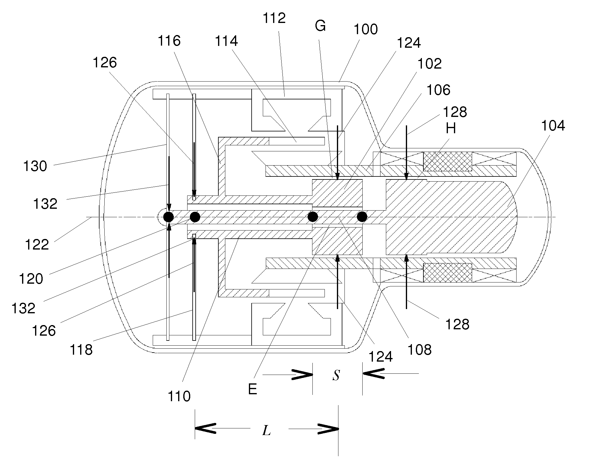
[0041]FIG. 5 illustrates a free-piston Stirling cycle machine having the improved bearing support system of the invention. The machine includes a casing 100 containing a cylindrical, free, power piston 102, a displacer piston 104 and other moving parts and is hermetically sealed to retain the working gas. Each piston is reciprocatable in a cylinder 106 mounted to the casing 100 and has a clearance seal with a seal length and an axial center. The piston 102 is supported by gas bearings at close fit clearance G in order to maintain a non-contact, close-fit with cylinder 106 and provide a clearance seal. Gas bearings are also provided at the interfaces at the close fit clearance H around the displacer piston 104 (about 25 μm diametrical clearance, typically) in order to maintain non-contact, close-fit with cylinder 106 and provide a clearance seal. In this case, the diametrical clearance E between the displacer rod 108 and the piston 102 can be more generous, for example 50 μm to 100 μ...


PUM


Abstract

A bearing support system for a piston and its connecting rod in which the bearing system supports the combined piston and connecting rod by only two bearings, a gas bearing at the power piston (or displacer) and a radially acting spring bearing at its connecting rod. The spacing between them meets prescribed relationships and preferably exceeds a calculated value based upon chosen engineering parameters. A non-compliant connecting rod is fixed to an end of a piston which has a clearance seal length in the range of 0.3 times the diameter of the piston and 1.5 times the diameter of the piston. The distance from the gas bearing to the effective point of connection of the radially acting spring bearing to the connecting rod is greater than the seal length of the piston. The allowable off-center distance A for the radial displacement of the fixed connection of the radially acting spring bearing to the connecting rod is considerably greater than the diametrical clearance gap g which illustrates the reduction in the required precision for adjusting the position of the radially acting spring bearing. The piston and connecting rod unit is not supported by additional bearings that introduce additional alignment problems.

Description

BACKGROUND OF THE INVENTION[0001]This invention relates generally to free-piston Stirling machines and more particularly relates to non-contact bearing support systems that support their power piston and / or displacer piston and their respective connecting rods attached to them. The invention improves the life, reliability and cost of free-piston machinery by providing a simple and reliable means to implement non-contact bearings in a manner that reduces the difficulty of aligning the bearings or allows more accurate alignment or both.[0002]Although free-piston Stirling cycle machines have been shown in the prior art in a very extensive variety of configurations, most have a displacer piston and a power piston that reciprocate in the same cylinder or in different cylinders. An end of the power piston and often an end of the displacer piston is ordinarily rigidly fixed to a connecting rod that reciprocates with the piston. These components together as a unit are supported within a cas...

Claims


Application Information

Patent Timeline
Patent Type & Authority Applications(United States)
IPC IPC(8): F02G1/04
CPCF02G1/0435F02G2280/10F02G2275/20
Inventor BERCHOWITZ, DAVID M.KWON, YONG-RAK
Owner GLOBAL COOLING
Why Eureka
Try Eureka