
Developing device, and controlling method thereof

a technology of developing device and controlling method, which is applied in the direction of instruments, electrographic process apparatus, optics, etc., can solve the problems of fogging or other problems, the performance of giving electric charges onto the toner is reduced, and the toner is deteriorated, etc., to achieve stable development

Active Publication Date: 2011-03-10
KONICA MINOLTA BUSINESS TECH INC
View PDF23 Cites 9 Cited by
  • Summary
  • Abstract
  • Description
  • Claims
  • Application Information

AI Technical Summary

Benefits of technology

[0013]Thus, a main object of this invention is to provide a developing device in a hybrid developing manner using a two-component developer containing a toner and a carrier in which, even when the length of a gap between a transporting roller, and a developing roller is varied, the generation of an image memory or leakage due to the gap variation therebetween can be restrained so that a stable development can be attained.

Problems solved by technology

However, in the one-component developing manner, the toner receives intense stress in the regulating region so that a deterioration in the toner is promoted.
Moreover, the surface of the regulating plate or the surface of the developing roller is contaminated by the toner or some other external additive, so that the performance of giving electric charges onto the toner lowers.
Thus, fogging or other problems are caused.
As a result, the lifespan of the developing device becomes relatively short.
Additionally, in the one-component developing manner, the gap length of a developing spatial region formed between the developing roller and an electrostatic latent image carrying member opposite to this roller is varied with the passage of time so that density unevenness may be generated in obtained images.
However, in the two-component developing manner also, the carrier is gradually contaminated with the toner or the other external additives after the developer is used over a long term.
As a result, the charge amount of the toner falls so that fogging or other problems may be caused.
When the gap length of the opposite spatial region, which is formed between the transporting roller and the developing roller, becomes larger than a predetermined value in the developing device of the hybrid developing manner, it may become insufficient to collect the toner fraction remaining on the developing roller onto the transporting roller after the development.
On the other hand, when the gap length between the transporting roller and the developing roller becomes smaller than a predetermined value, a leakage may be generated therebetween.

Method used


Image

  • Developing device, and controlling method thereof
  • Developing device, and controlling method thereof
  • Developing device, and controlling method thereof

Examples


Embodiment Construction

[0025]With reference to the attached drawings, preferred embodiments of the invention will be described hereinafter. In the description, the words “upper, over, above or on”, “lower, under, below or beneath”, “left” and “right”, any wording including one or more of these words, the word “clockwise”, the word “counterclockwise”, and words or wordings each meaning a specified side or direction may be used; however, the use thereof is for making the understanding of the invention described with reference to the drawings easy, and the invention should not be interpreted to be restricted by the meanings of these words.

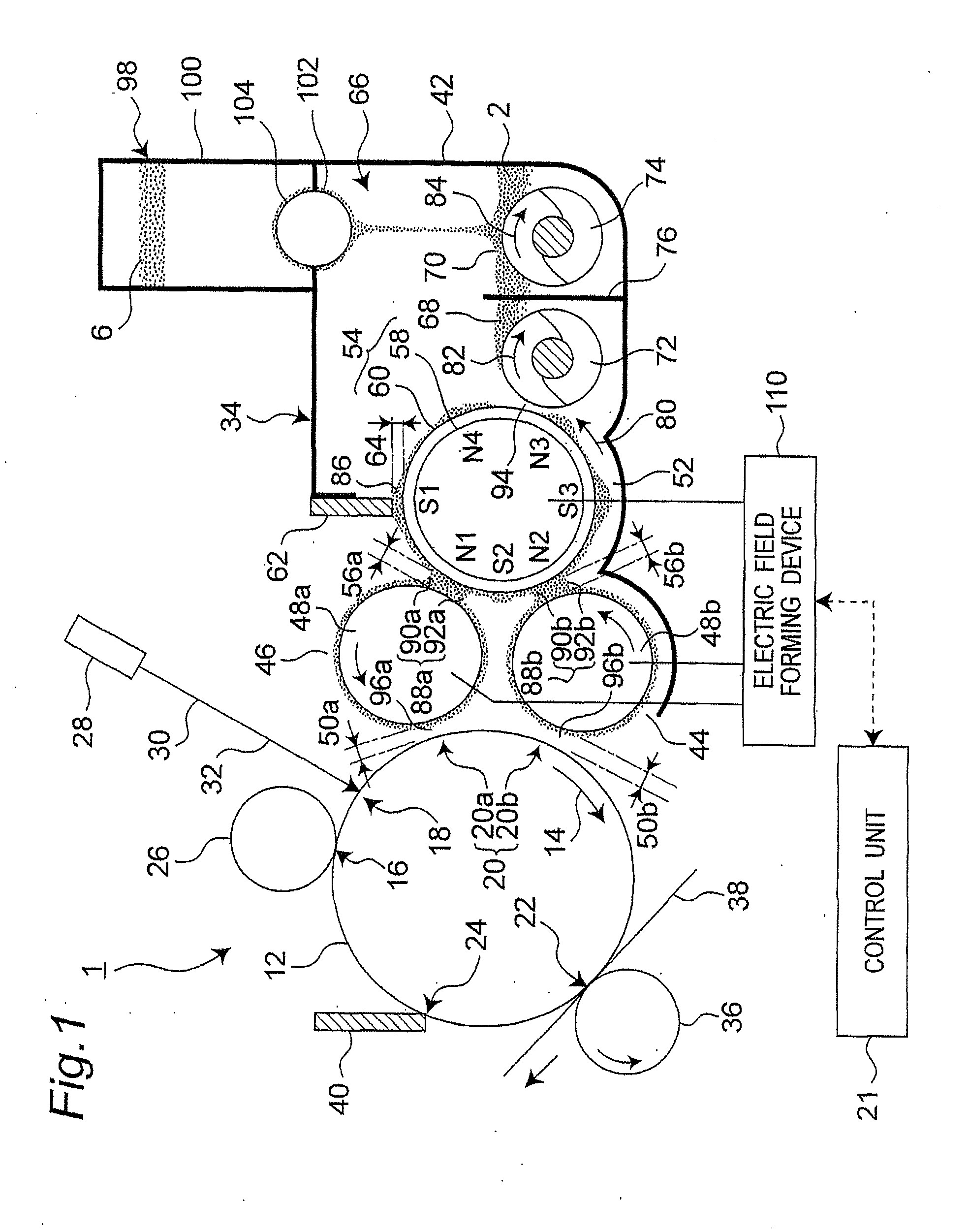
[0026]FIG. 1 is a view illustrating a schematic structure of an image forming apparatus including a developing device according to an embodiment of the invention. The image forming apparatus may be any one of a copying machine, a printer, facsimile, and a multifunctional apparatus having two or more of functions of these machines or apparatus. An image forming apparatus 1 h...


PUM


Abstract

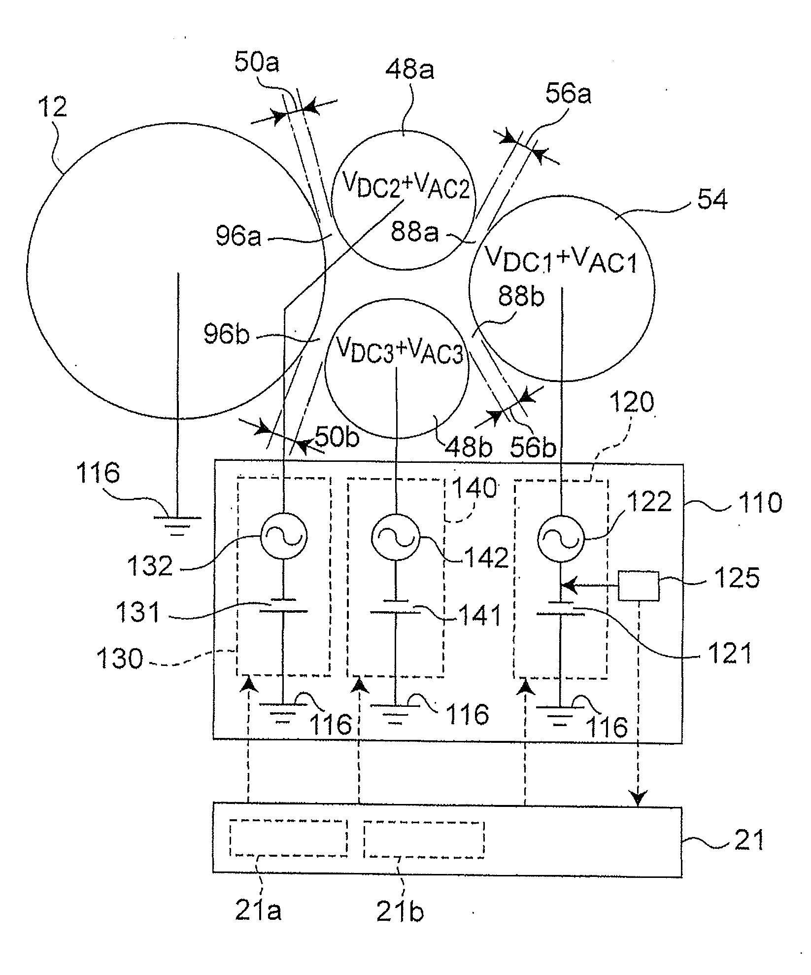
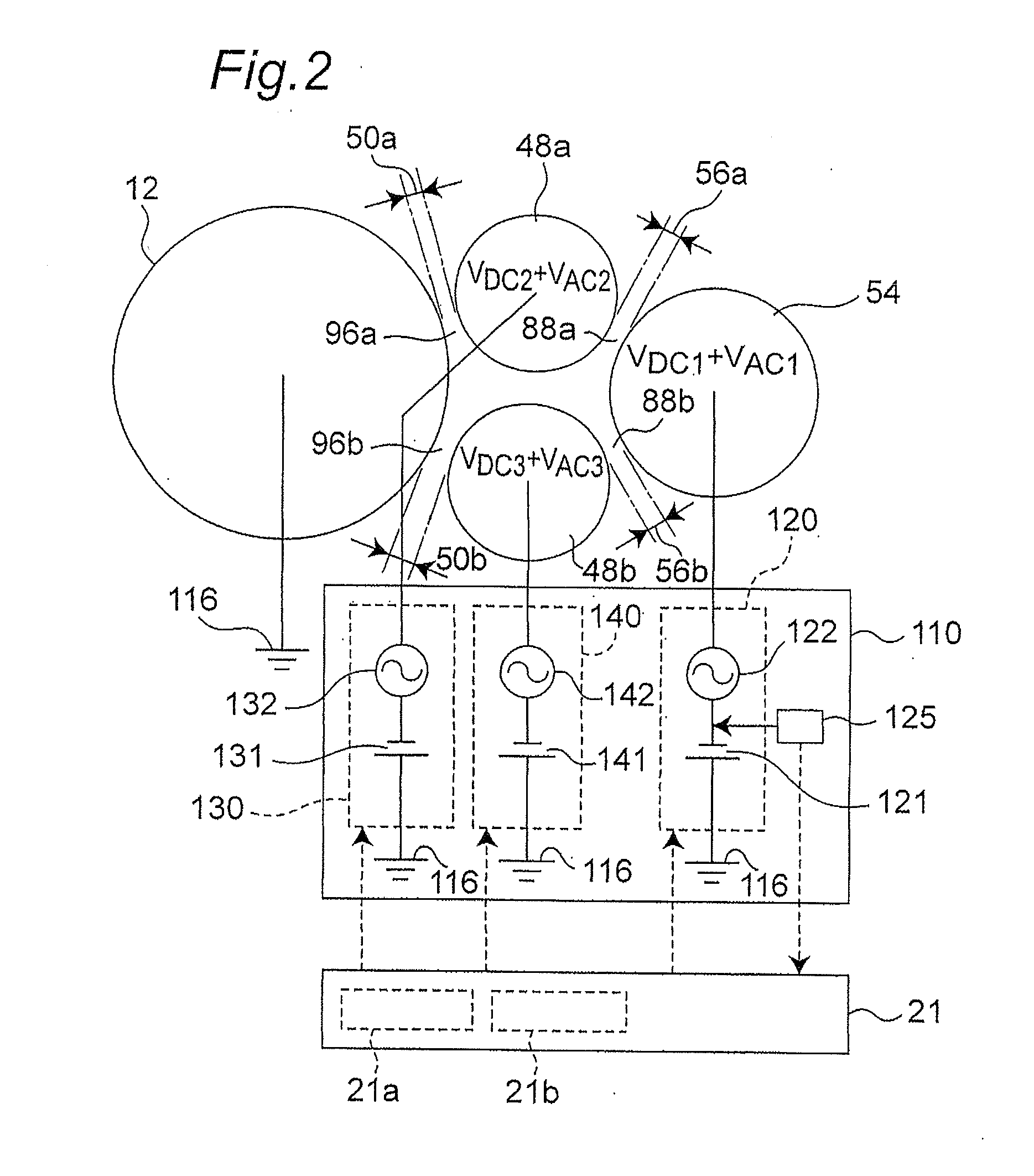
A developing device is provided with a developer transporting member for transporting a developer containing a toner and a carrier; a toner transporting member opposite to the developer transporting member and opposite to an electrostatic latent image carrying member; a first electric field forming device, which is composed of a power source for the developer transporting member and a power source for the toner transporting member, for shifting the toner in the developer held onto the developer transporting member to the toner transporting member; and a second electric field forming device for shifting the toner held onto the toner transporting member to an electrostatic latent image on the carrying member. Operation of the first electric field forming device is controlled based on an electric current flowing in the developer transporting member power source, which is detected by a detecting block.

Description

CROSS-REFERENCE TO RELATED APPLICATION[0001]This application is based on Japanese Patent Application No. 2009-205701 filed in Japan, the content of which is incorporated herein by reference.BACKGROUND OF THE INVENTION[0002]1. Field of the Invention[0003]The present invention relates to a developing device used in an image forming apparatus in an electrophotographic manner, such as a copying machine, a printer, a facsimile, or a multifunctional machine wherein two or more thereof are combined with each other; and a controlling method thereof.[0004]2. Description of the Related Art[0005]Regarding a developing device used in an image forming apparatus in an electrophotographic manner, hitherto, as a developing manner of developing an electrostatic latent image formed on an electrostatic latent image carrying member, the following have been known: a one-component developing manner in which only a toner is used as a main component of a developer (or developing agent), and a two-component...

Claims


Application Information

Patent Timeline
Patent Type & Authority Applications(United States)
IPC IPC(8): G03G15/08
CPCG03G15/065G03G2215/0648G03G2215/0607G03G15/0806
Inventor IMURA, TOMOYUKISAITO, KAZUHIROOKADA, TAKUYASASAKI, TAKUYATSUTSUI, CHIKARATAKAI, TAKAYUKI
Owner KONICA MINOLTA BUSINESS TECH INC
Learn More