Power supply circuit for supplying power to electronic device such as image forming apparatus

a technology of power supply circuit and electronic device, which is applied in the direction of electrographic process apparatus, instruments, optics, etc., can solve the problems of blunt rectangular wave poor charging efficiency, damage to latent image, disadvantages of damping resistor use, etc., and achieve stable development and reduce dependence on damping resistor

Inactive Publication Date: 2012-03-22
CANON KK
View PDF1 Cites 6 Cited by
  • Summary
  • Abstract
  • Description
  • Claims
  • Application Information

AI Technical Summary

Benefits of technology

[0010]It is a feature of the present invention to achieve stable development while decreasing dependence on a damping resistor by suppressing a shape distortion of a blank pulse waveform.

Problems solved by technology

This is because various problems arise if an applied voltage greatly exceeds a target voltage to generate an overshoot.
Also, aerial discharge occurs in a conductive impurity mixed in a developing agent, damaging a latent image.
However, the use of the damping resistor also has disadvantages.
The blunt rectangular wave is poorer in charging efficiency than the ideal rectangular wave.
The power loss across the damping resistor accounts for half the input power to an AC voltage generation circuit, increasing the space for permitting the energy loss and raising the component cost.
However, a problem arises when the conventional technique is applied to a so-called blank pulse waveform having a pulse period during which a rectangular wave is output and a blank period during which output of a rectangular wave stops.
Such a waveform distortion degrades the developing quality, as described above.

Method used


Image

  • Power supply circuit for supplying power to electronic device such as image forming apparatus
  • Power supply circuit for supplying power to electronic device such as image forming apparatus
  • Power supply circuit for supplying power to electronic device such as image forming apparatus

Examples


first embodiment

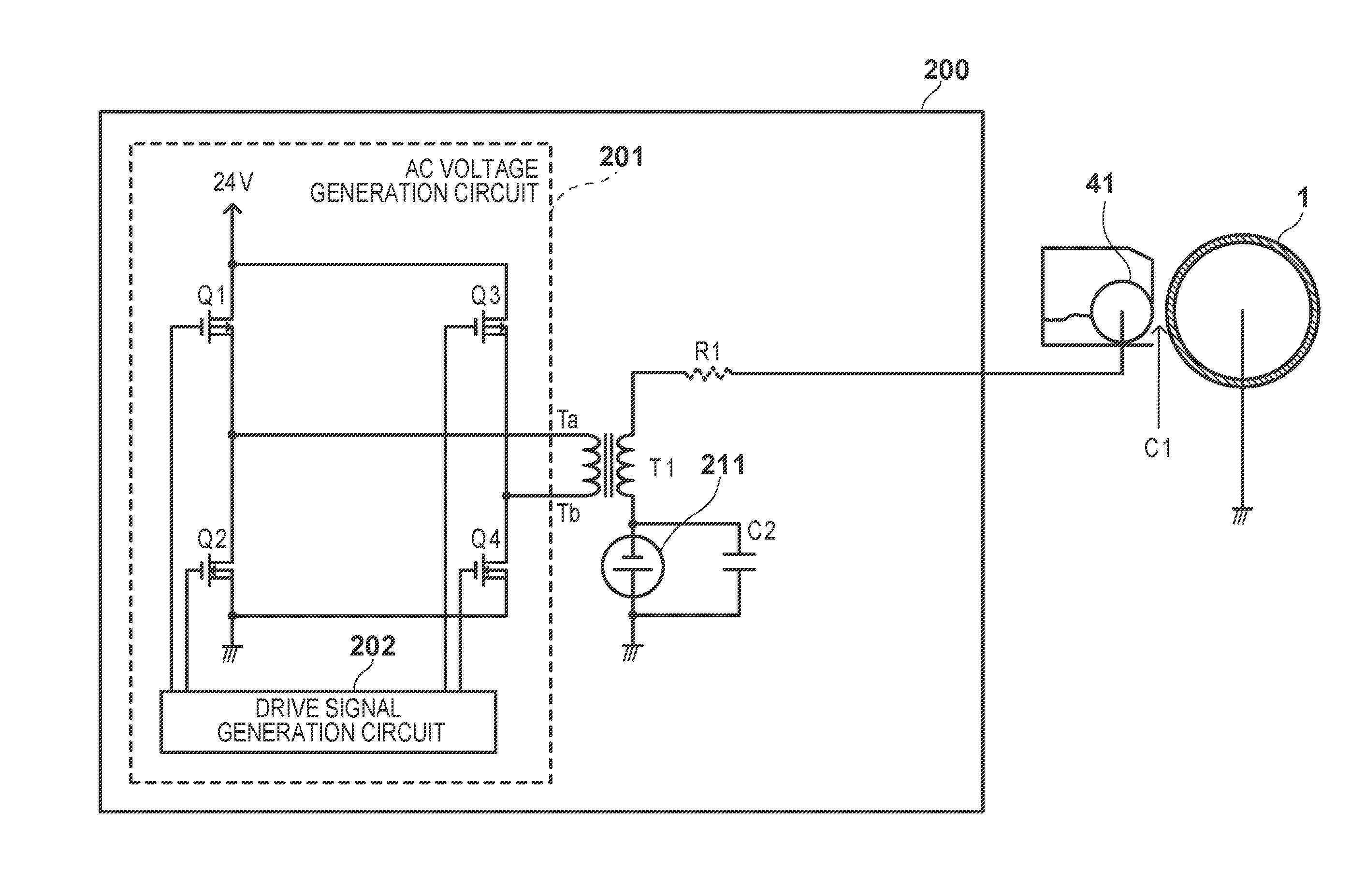
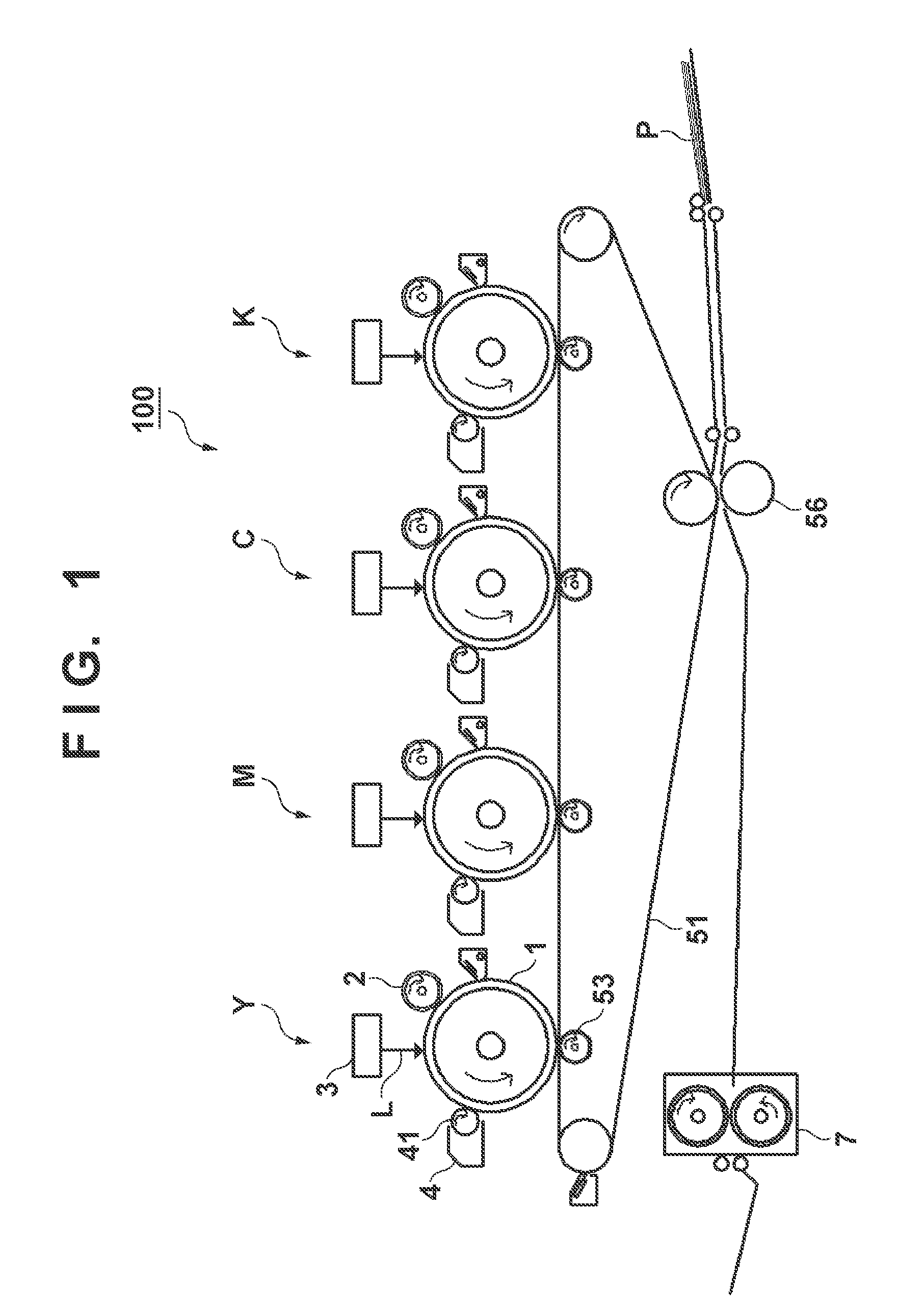
[0021]An image forming apparatus 100 shown in FIG. 1 is an electrophotographic multi-color image forming apparatus including a power supply circuit according to the present invention. Note that the present invention is applicable to even a monochrome image forming apparatus. The image forming apparatus 100 includes four image forming stations Y, M, C, and K which form images with developing agents (toners) of different colors, that is, yellow, magenta, cyan, and black. The image forming stations have basically the same arrangement, and the yellow image forming station will be explained as a representative.

[0022]When a host controller 210 (FIG. 2) which controls the overall image forming apparatus 100 receives an instruction to form an image on a printing medium P, a photosensitive member 1, intermediate transfer belt 51, charging roller 2, developing sleeve 41, primary transfer roller 53, secondary transfer roller pair 56, and fixing unit 7 start rotating. A DC voltage or a high vol...

second embodiment

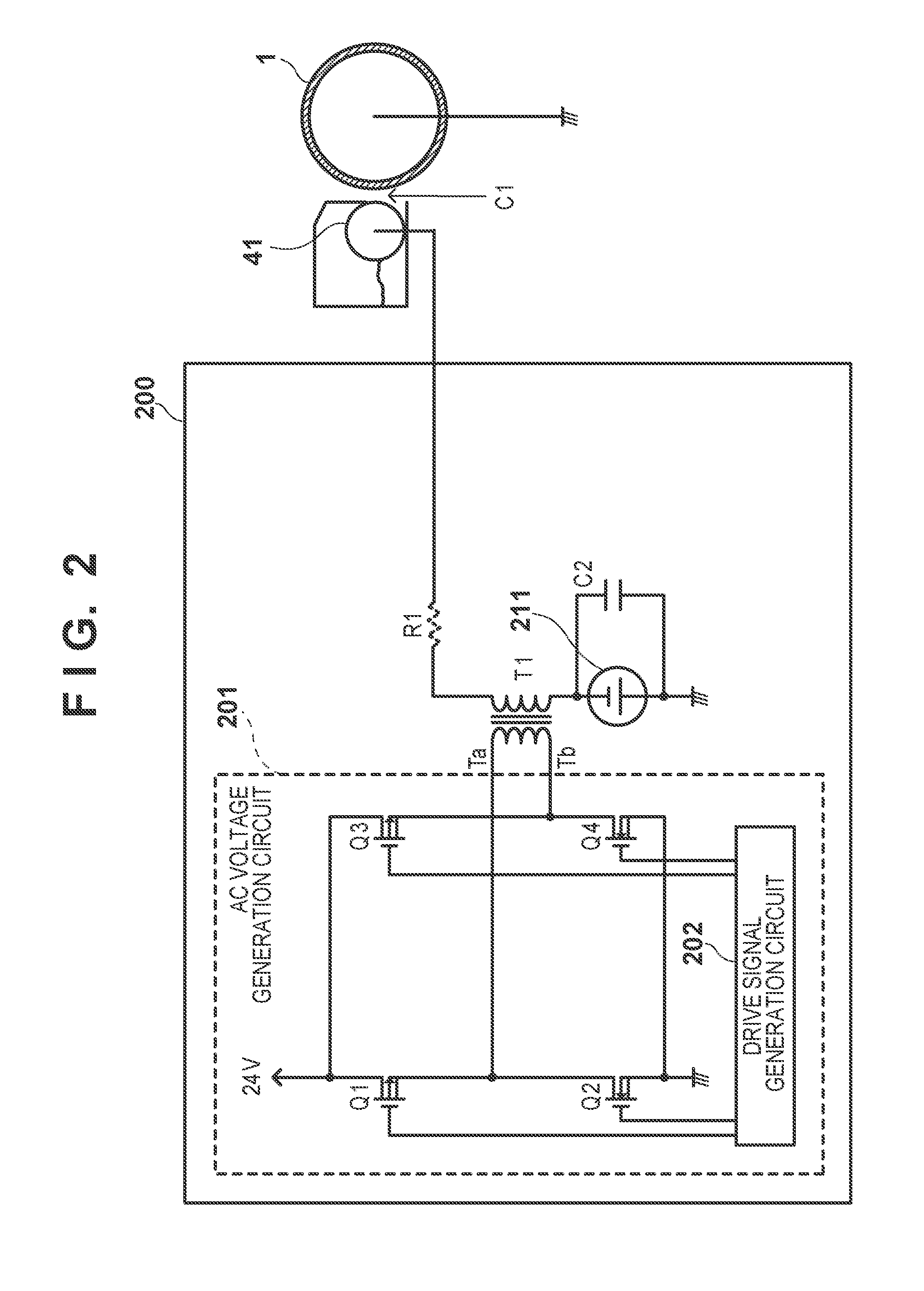
[0041]FIG. 5 is a schematic view showing a power supply device, a developing unit 4, and a photosensitive member 1 according to the second embodiment. In FIG. 2, a single voltage of 24 V is supplied to both Q1 and Q3. In FIG. 5, 18 V is applied to the drain of Q1, 12 V is applied to the drain of Q3, and a capacitor C3 is series-connected to a transformer T1. The remaining arrangement in the second embodiment is the same as that in the first embodiment.

[0042]The capacitance value of the added capacitor C3 is set to a value large enough not to change the voltage across the capacitor C3 from a potential difference of 6 V between the two power supply voltages of 18 V and 12 V, in order to suppress a change of the voltage across the capacitor C3 caused by a switching operation by semiconductor switching elements Q1, Q2, Q3, and Q4.

[0043]FIG. 6 is a waveform chart showing the pattern of a gate signal output from a drive signal generation circuit 202 and an output voltage waveform accordin...


PUM


Abstract

A developing unit develops a latent image with a developing agent. A supply unit supplies, to the developing unit, a developing alternating current bias voltage with a waveform having a pulse period during which a rectangular wave is output and a blank period during which no rectangular wave is output. An input signal generation unit generates, as an input signal be supplied to a primary side of a transforming unit that forms the developing alternating current bias voltage, an input signal obtained by adding an additional pulse smaller in width than the rectangular wave in the pulse period at a timing to transit from the pulse period to the blank period.

Description

BACKGROUND OF THE INVENTION[0001]1. Field of the Invention[0002]The present invention relates to a power supply circuit for supplying power to an electronic device such as an image forming apparatus.[0003]2. Description of the Related Art[0004]A developing device in an electrophotographic or electrostatic printing image forming apparatus efficiently develops an electrostatic latent image with toner by applying, to a developing sleeve, a voltage in which DC (Direct Current) and AC (Alternating Current) voltages are superposed. In particular, an AC voltage having a rectangular waveform increases the charging efficiency of toner with respect to a latent image (ratio at which toner charges couple with latent image charges).[0005]A voltage applied to the developing sleeve needs to have a target value. This is because various problems arise if an applied voltage greatly exceeds a target voltage to generate an overshoot. For example, a current flows through an unintended conductor via the ...

Claims


Application Information

Patent Timeline
Patent Type & Authority Applications(United States)
IPC IPC(8): G03G15/00G03G15/08
CPCG03G15/065G03G15/01G03G15/06
Inventor OKUMURA, YASUHIKO
Owner CANON KK
Why Eureka
Try Eureka