Methods to increase force and change vibratory separator motion

a technology of vibratory separator and motion, which is applied in the direction of mechanical vibration separation, adaptive control, instruments, etc., can solve the problems of time-consuming and expensive mud evaluation and mixture process, too light may not protect, and too heavy may over-invade the formation,

Active Publication Date: 2011-03-10
MI
View PDF14 Cites 13 Cited by
  • Summary
  • Abstract
  • Description
  • Claims
  • Application Information

AI Technical Summary

Problems solved by technology

Drilling mud that is too light may not protect the formation from blow outs, and drilling mud that is too heavy may over invade the formation.
Because the mud evaluation and mixture process is time consuming and expensive, drillers and service companies prefer to reclaim the returned drilling mud and recycle it for continued use.
Over time, the stress points caused by the basket mounted motors may result in structural failure of the basket.
Such structural failure may require taking the shaker out of service, thereby resulting in expensive and time consuming repairs.

Method used


Image

  • Methods to increase force and change vibratory separator motion
  • Methods to increase force and change vibratory separator motion
  • Methods to increase force and change vibratory separator motion

Examples


Embodiment Construction

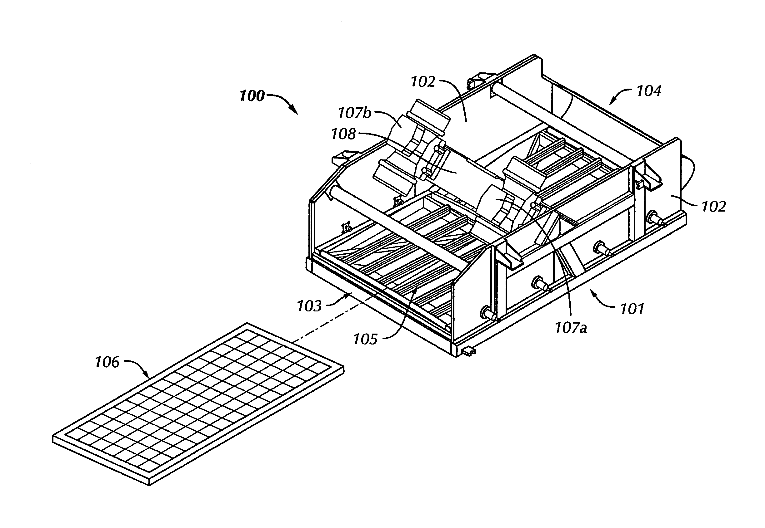
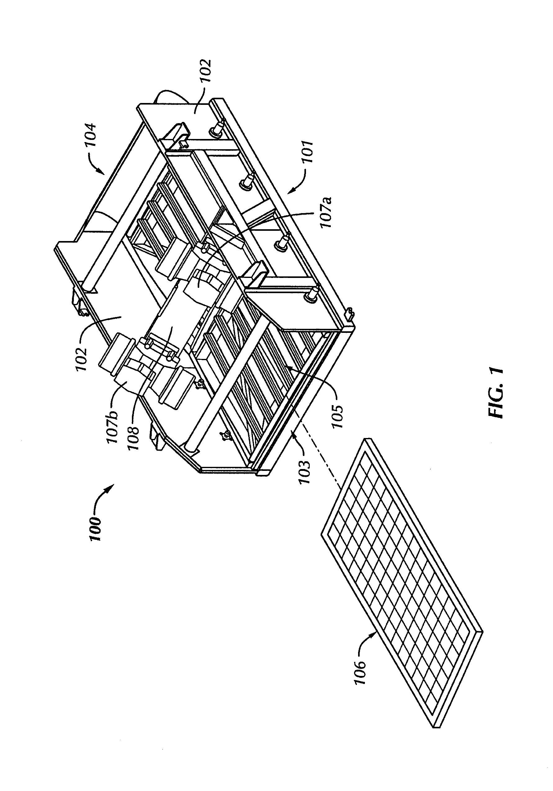
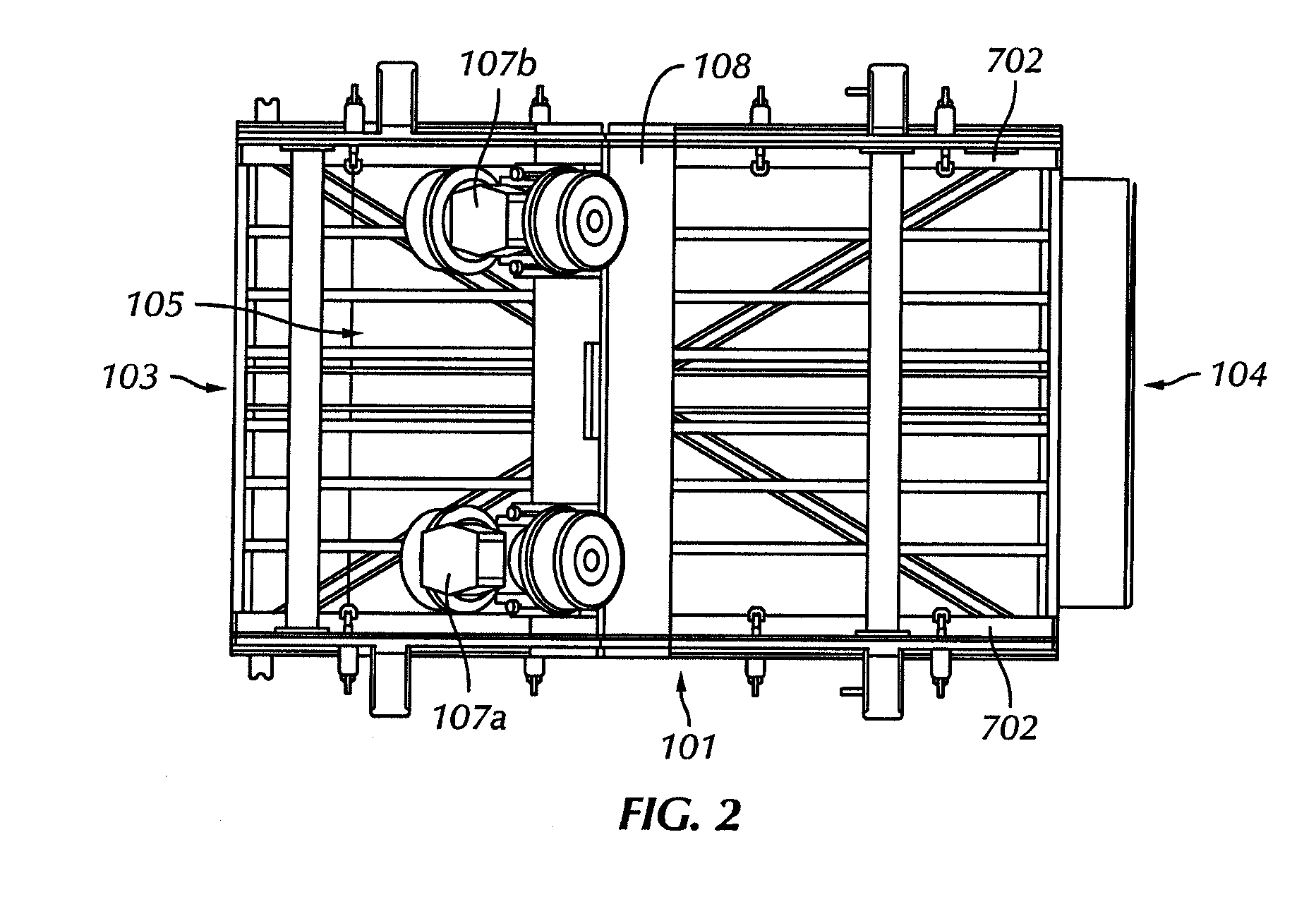
[0025]Generally, embodiments disclosed herein relate to apparatuses and methods for separating solids from liquids. Specifically, embodiments disclosed herein relate to apparatuses and methods using a variable frequency drive to control a direction of motion of a basket of a vibratory separator.

[0026]Referring initially to FIGS. 1-4, isometric, top, side and front views of a vibratory separator 100 in accordance with an embodiment of the present disclosure are shown. In this embodiment, vibratory separator 100 includes a frame 101, side walls 102, a discharge end 103, and an inlet end 104. Vibratory separator 100 also includes a basket 105 that holds a screen assembly 106. Operationally, as drilling material enters vibratory separator 100 through inlet end 104, the drilling material is moved along screen assembly 106 by a vibratory motion. As screen assembly 106 vibrates, residual drilling fluid and particulate matter may fall through screen assembly 106 for collection and recycling...


PUM


Abstract

A vibratory separator including a frame, a basket disposed on the frame, and a motor configured to impart a vibratory motion to the basket. Additionally, the vibratory separator includes an adjustable speed drive operatively coupled to the motor to control a vibratory motion imparted to the basket. Also, a method of processing drilling waste including generating a first vibratory motion on a vibratory separator using at least one motor, and adjusting the first vibratory motion using an adjustable speed drive to generate a second vibratory motion.

Description

BACKGROUND[0001]1. Field of the Disclosure[0002]Generally, embodiments of the present disclosure relate to apparatuses and methods for separating solids from fluids. More specifically, embodiments of the present disclosure relate to apparatuses and methods for providing a vibratory motion to a vibratory shaker using adjustable speed drives.[0003]2. Background Art[0004]Oilfield drilling fluid, often called “mud,” serves multiple purposes in the industry. Among its many functions, the drilling mud acts as a lubricant to cool rotary drill bits and facilitate faster cutting rates. Typically, the mud is mixed at the surface and pumped downhole at high pressure to the drill bit through a bore of the drillstring. Once the mud reaches the drill bit, it exits through various nozzles and ports where it lubricates and cools the drill bit. After exiting through the nozzles, the “spent” fluid returns to the surface through an annulus formed between the drillstring and the drilled wellbore.[0005]...

Claims


Application Information

Patent Timeline
Patent Type & Authority Applications(United States)
IPC IPC(8): B07B1/28G05D19/02
CPCB07B1/42B06B1/161B07B1/28C02F1/34
Inventor BURKHARD, ALAN WAYNE
Owner MI
Why Eureka
Try Eureka