Hand puller with a structure of double stopping plates

a technology of stopping plate and hand puller, which is applied in the direction of fastenings, press-button fasteners, transportation items, etc., can solve the problems of increasing the cost of hand pullers and releasing straps too much

Inactive Publication Date: 2011-03-17
WIN CHANCE METAL
View PDF6 Cites 4 Cited by
  • Summary
  • Abstract
  • Description
  • Claims
  • Application Information

AI Technical Summary

Benefits of technology

An objective of the invention is to provide a hand puller with a structure of double stopping plates to achieve the effect of engaging and stopping its ratchet with the two stopping plates when the hand puller holds its strap.
Another objective of the invention is to provide a slow strap release mechanism at the fixing part so that the driving claw of the pulling part can shift in the stroke and the ratchet can back the strap out tooth by tooth.

Problems solved by technology

This increases the cost of the hand puller.
Without appropriate control, the strap may be released too much.

Method used


Image

  • Hand puller with a structure of double stopping plates
  • Hand puller with a structure of double stopping plates
  • Hand puller with a structure of double stopping plates

Examples


Embodiment Construction

The present invention will be apparent from the following detailed description, which proceeds with reference to the accompanying drawings, wherein the same references relate to the same elements.

Please refer to FIGS. 1 to 7 for an embodiment of the invention. It is used only for the illustration purpose. The invention is not restricted to such a structure.

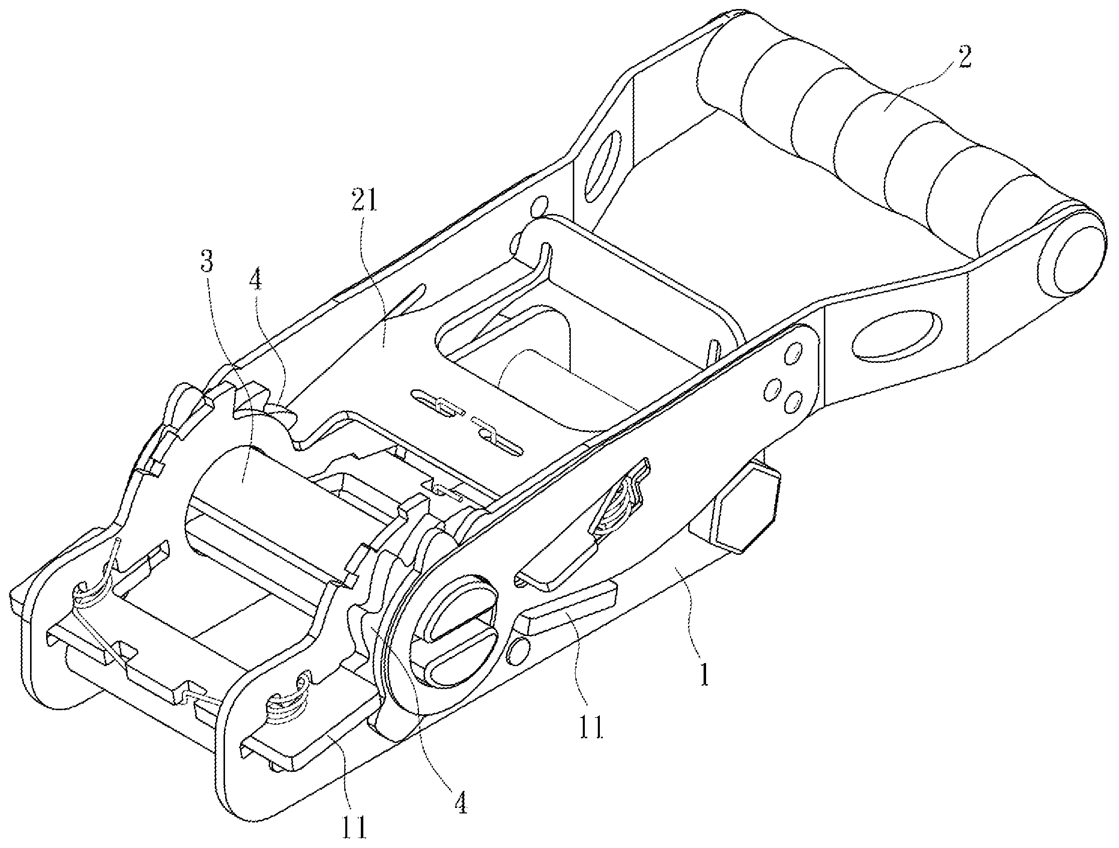
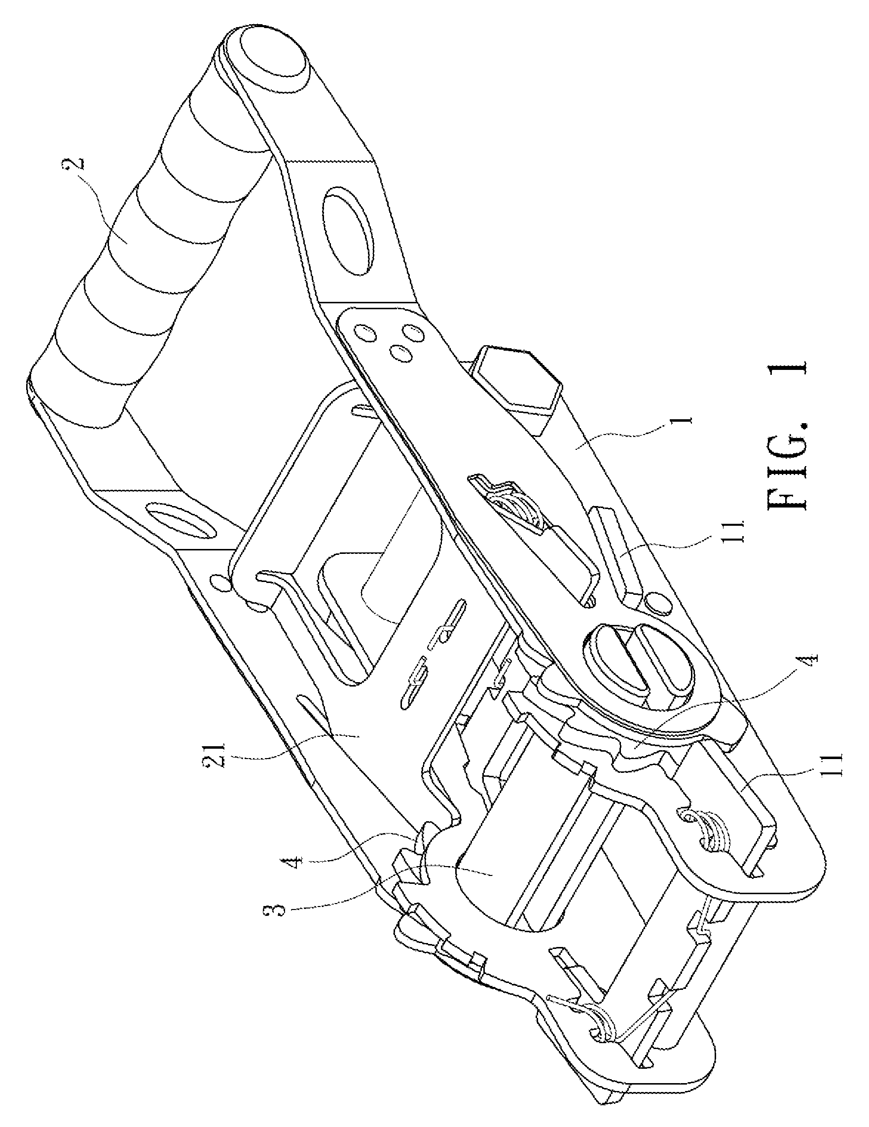
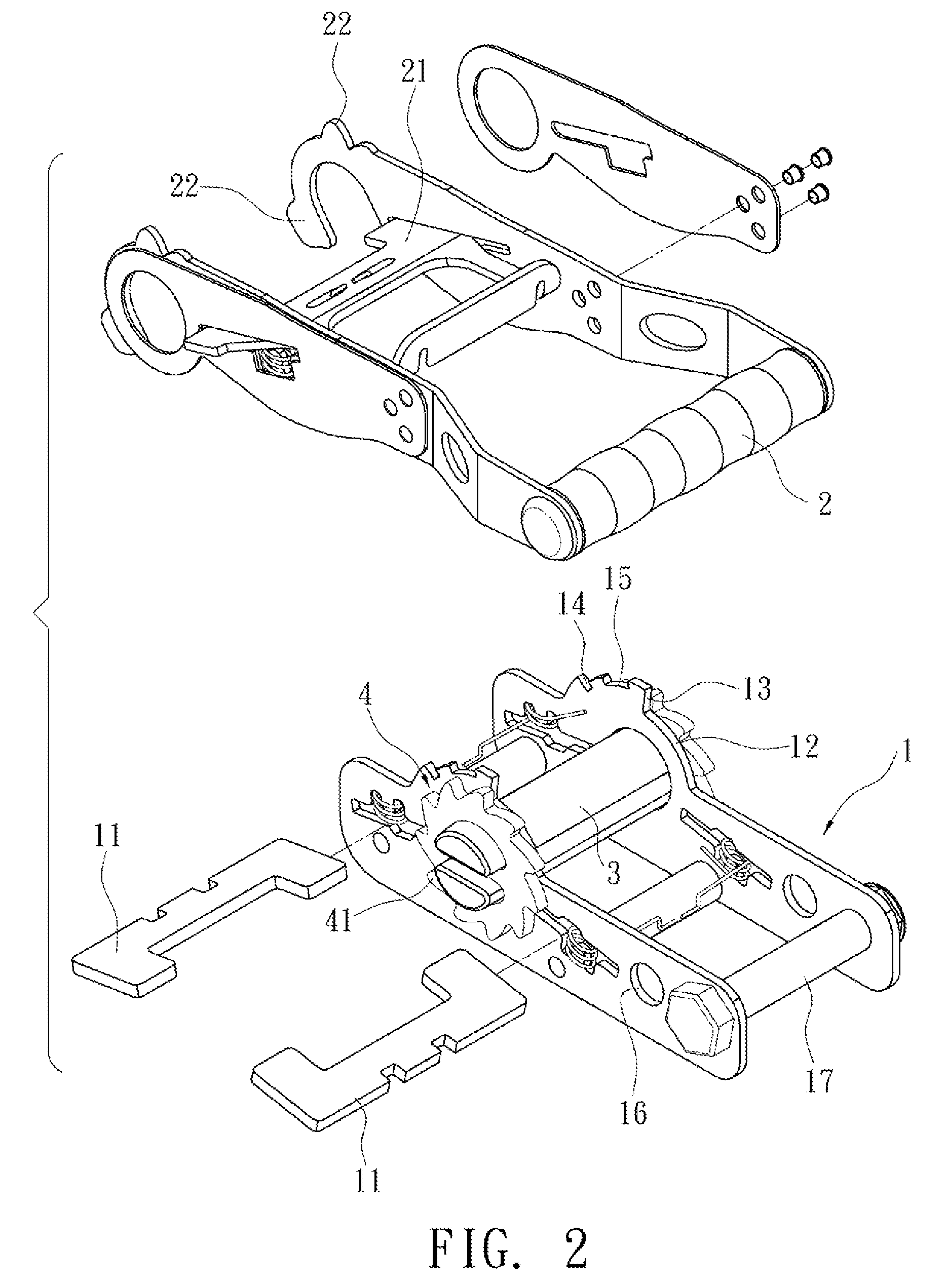
This embodiment provides an improved hand puller. An axle part 3 goes through a fixing part I and a pulling part 2. Both ends of the axle part 3 are provided with a ratchet 4, respectively. The fixing part 1 has stopping plates I1. The pulling part 2 has a driving claw 21. The stopping plate 11 and the driving claw 21 engage with the teeth 41 of the ratchet 4. As shown in FIG. 2, the pulling part 2 can depart from the fixing part 1.

The fixing part 1 has a stopping plate 11 ob opposite ends of the axle 3, respectively. When the driving claw 21 drives the ratchet 4, the stopping plate 11 on one side of the ratchet 4 engages with the...


PUM


Abstract

A hand puller with the structure of double stopping plates is disclosed. An axle part goes through a fixing part and a pulling part. Both ends of the axle part have a ratchet, respectively. The fixing part has two stopping plates, fixed to the two opposite sides of the axle part. The pulling part has a driving claw. The driving claw and the stopping plates of the fixing part engage with the ratchet.

Description

BACKGROUND OF THE INVENTION1. Field of InventionThe invention relates to a hand puller and, in particular to a hand puller with an improved structure of double stopping plates.2. Related ArtFIG. 11 shows a conventional hand puller. Its fixing part 80 and pulling part 81 are joined with an axle part 82. The axle part 82 has a ratchet 83. The fixing part 80 has a stopping plate 85. The pulling part 81 has a driving claw 86. The stopping plate 85 and the driving claw 86 engage with the ratchet 83.As shown in the structure, the puller has only one stopping plate 85. The stopping plate 85 may not accurately engage with the ratchet 83 because there is some variation in the tooth span. When the puller is tightened, the stopping plate 85 may depart from the ratchet so that the strap falls off.FIG. 12 shows another conventional hand puller. The fixing part 90 has two stopping plates 91 installed on the same side of the ratchet 92. They engage with the ratchet 92 from top and bottom, respecti...

Claims


Application Information

Patent Timeline
Patent Type & Authority Applications(United States)
IPC IPC(8): A44B11/02
CPCY10T24/2175B60P7/083
Inventor CHANG, WEN-CHENG
Owner WIN CHANCE METAL
Why Eureka
Try Eureka