Attachment system used to mount accessory devices to a firearm

a technology of accessory devices and mounting systems, which is applied in the direction of gun mounting, ammunition loading, butts, etc., can solve the problems of operator's inability to engage/disengage the latching mechanism, difficult, not only for the operator to continue to hold the weapon, etc., to achieve the effect of maintaining or improving the alignment of the boresigh

Inactive Publication Date: 2011-03-17
NITESCOUT
View PDF9 Cites 64 Cited by
  • Summary
  • Abstract
  • Description
  • Claims
  • Application Information

AI Technical Summary

Benefits of technology

[0009]Another object of the invention is to provide a mechanism for attaching an auxiliary device to a weapon such that the accessory device will maintain or better maintain boresight alignment even after shocks of repeated weapon fire recoils.
[0010]Another object of the invention is to provide a mechanism for mounting an accessory device to a weapon without temporary or permanent disassembly or removal of any parts of the weapon to which the accessory device is attached.

Problems solved by technology

In addition, the inventors' have discovered that current attachment systems require the operator to engage / disengage the latching mechanism using two fingers; none permit the operator to engage / disengage the latching mechanism using only one finger.
As a result, current attachment systems make it difficult, not only for the operator to continue to hold the weapon via the weapon's grip (generally used by the hand that operates the trigger) while adding or removing an accessory device, but also to engage or disengage the latching mechanism, all while on the move in combat.

Method used


Image

  • Attachment system used to mount accessory devices to a firearm
  • Attachment system used to mount accessory devices to a firearm
  • Attachment system used to mount accessory devices to a firearm

Examples


Embodiment Construction

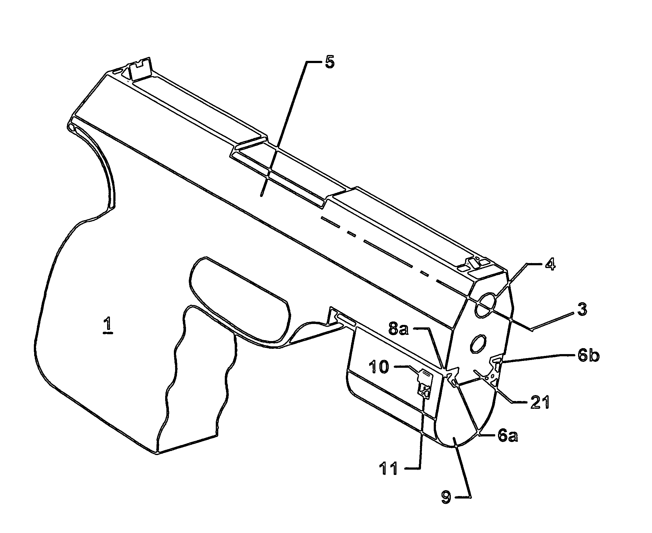
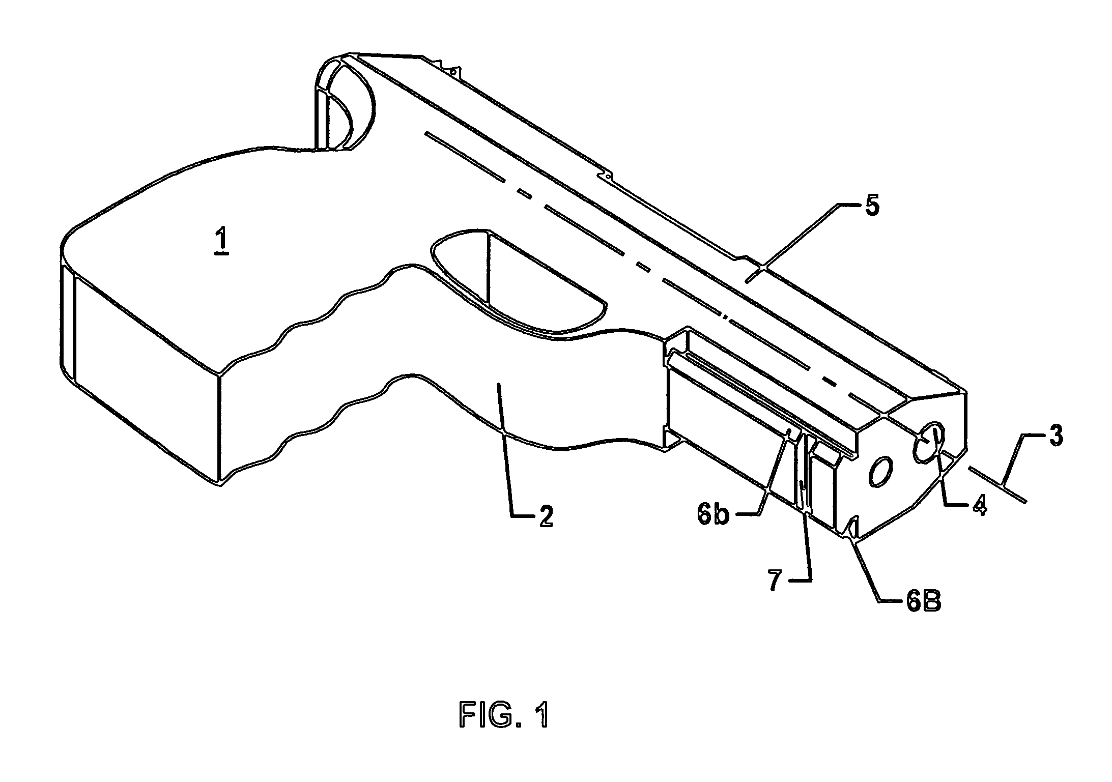
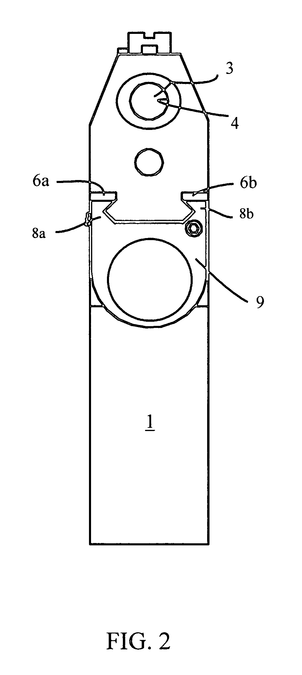
[0021]Turning first to FIG. 1, there is illustrated an example of a firearm 1, specifically a handgun including a barrel 4 extending along a longitudinal axis 3 from the handgun's frame 5. The handgun 1 includes a trigger guard 2 in front of the handgun's trigger.

[0022]As used herein, “longitudinal” describes a direction along or parallel to the longitudinal axis 3 of the firearm's barrel 4; “transverse” describes a horizontal direction perpendicular to the axis 3 when the barrel 4 (or accessory device 9) is horizontally positioned; “above” means vertically above and “upward” means vertically upward when the firearm barrel 4 (or accessory device 9) is horizontally positioned; “below” or “beneath” means vertically below; “front” and “forward” describes the longitudinal direction toward the muzzle of the barrel 4 or the accessory device 9 (i.e., to the right as shown in FIGS. 1 & 3); “rear” or “rearward” describes the longitudinal direction opposite the front or forward direction (i.e...


PUM


Abstract

An attachment system for mounting an accessory device to a longitudinal rail along the frame and forwardly of a trigger guard; said rail configured with at least two longitudinal grooves, one along each side of the rail, and further configured with a transverse slot in the surface of the rail; an accessory including a pair of longitudinal tongues, said tongues complimenting the longitudinal grooves for retaining the accessory device on the rail; a compression spring in a recess area formed in said accessory upwardly biasing a latch, on the accessory device housing and pivoting on a pivot pin; said latch containing a transversely disposed elongated protuberance having a width slightly less than the transverse slot of said rail for being received therein that co-acts with the transverse slot in said rail to prevent further longitudinal movement of the accessory device along the rail.

Description

CROSS-REFERENCE TO RELATED APPLICATIONS[0001]This is application claims the priority benefit under 35 U.S.C. §119(e) of U.S. Provisional Application No. 61 / 241,653, Apparatus For Securing Accessories to a Firearm, filed on Sep. 11, 2009, each of the entire disclosures of which are hereby incorporated by reference herein.BACKGROUND OF THE INVENTION[0002]This invention relates to an attachment system used to mount accessory devices to a firearm including a handgun.[0003]Handgun manufacturers have introduced various handgun models having a longitudinal rail along the handgun's frame and forwardly of the trigger guard, such rail being configured with two longitudinal grooves, one along each side of the rail, and further configured with a transverse slot in the surface of the rail. Such rails are intended for accommodating accessories having a housing configured with a pair of longitudinal tongues complimenting the longitudinal grooves for retaining the accessory on the rail. The latch o...

Claims


Application Information

Patent Timeline
Patent Type & Authority Applications(United States)
IPC IPC(8): F41C27/00F41G1/00F41G1/387F41C23/12F41A23/12
CPCF41G11/003
Inventor CAVALLO, SANTUCCIOCAVALLO, ROBERT FRANK
Owner NITESCOUT
Why Eureka
Try Eureka