Friction reducing wear band and method of coupling a wear band to a tubular

a friction-reducing wear band and tubular technology, applied in the field of earthen borehole drilling and casing, can solve the problems of increasing frictional contact, exacerbate wear, damage or erosion of the outer surface of the tubular, etc., to reduce the torque demand for rotation, reduce frictional resistance, and reduce the effect of frictional resistan

Active Publication Date: 2010-10-07
INNOVEX DOWNHOLE SOLUTIONS INC
View PDF21 Cites 53 Cited by
  • Summary
  • Abstract
  • Description
  • Claims
  • Application Information

AI Technical Summary

Benefits of technology

[0014]Embodiments of the wear band and method of coupling a wear band to a tubular satisfy the above-stated needs. In one embodiment of the wear band, the bore of a rotating element is received onto a tubular having a non-upset end connection over which the wear band may be installed. The wear band comprises a rotating element having a bore and an exterior wear surface comprised of a friction reducing material such as, for example, but not limited to, hardened steel, nylon, plastic, composite or brass, to reduce frictional resistance to longitudinal sliding movement of the tubular through a bore, which may be, for purposes of the claims that follow, an earthen borehole or the bore of an installed section of casing. The bore of the rotating element may receive sleeve bearings radially intermediate the bore of the rotating element and the tubular to reduce frictional resistance to rotation of the rotating element on the tubular and, thus, to reduce the torque demand for rotation of a tubular string that includes the tubular within a borehole or within a bore of a casing.
[0015]In one embodiment of the method of installing a wear band, the wear band may be rotatably secured to a tubular intermediate a first stop collar and a second stop collar that straddle the sleeve bearings and the rotating element to limit or prevent longitudinal movement of the sleeve bearings and the rotating element. In one embodiment, the sleeve bearings may be rotatable within, but longitudinally coupled to, the rotating element to prevent longitudinal movement of the sleeve bearings relative to the rotating element. This embodiment may be used to prevent the rotating element from frictional contact with the tubular and / or the first and second stop collars, e.g., to isolate all sliding contact to the sleeve bearings. In another embodiment, the rotating element may be connected to the sleeve bearings using, for example, a connector, an adhesive or an interference fit.
[0016]Another embodiment of the wear band provides a rotating element having a bore comprising a bore first portion and a bore second portion separated one from the other by a shoulder. For example, the bore of the rotating element may comprise a bore first portion and a bore second portion separated one from the other by a radially inwardly protruding barrier, such as a protruding wall, within the bore of the rotating element. In this embodiment, a first sleeve bearing may be disposed radially intermediate the bore first portion and the tubular, and a second sleeve bearing may be disposed radially intermediate the bore second portion and the tubular, to contact the tubular and the rotating element and to together reduce frictional resistance to rotation of the rotating element on the tubular. In one embodiment, this configuration provides a rotating element that is maintained in its longitudinal position by engagement of the shoulder with the first and second sleeve bearings. This configuration prevents frictional engagement between the rotating element and the tubular or stop collars.

Problems solved by technology

There is a potential for damage or erosion of the outer surface of the tubular where the tubular is moved within the bore of an installed casing string when there is direct metal-to-metal contact.
However, casing is generally larger than drill pipe, thereby resulting in more frictional contact with the borehole, and the need to rotate the casing within the borehole may exacerbate wear.
's centralizer is that the body appears to slide along the tubular until it, and not a friction-reducing slider, engages an external feature on the tubular exterior, such as a sleeve-type tubular connection, another centralizer or a stop collar, resulting in unwanted friction between the rotating centralizer and that external feature.

Method used


Image

  • Friction reducing wear band and method of coupling a wear band to a tubular
  • Friction reducing wear band and method of coupling a wear band to a tubular
  • Friction reducing wear band and method of coupling a wear band to a tubular

Examples


Embodiment Construction

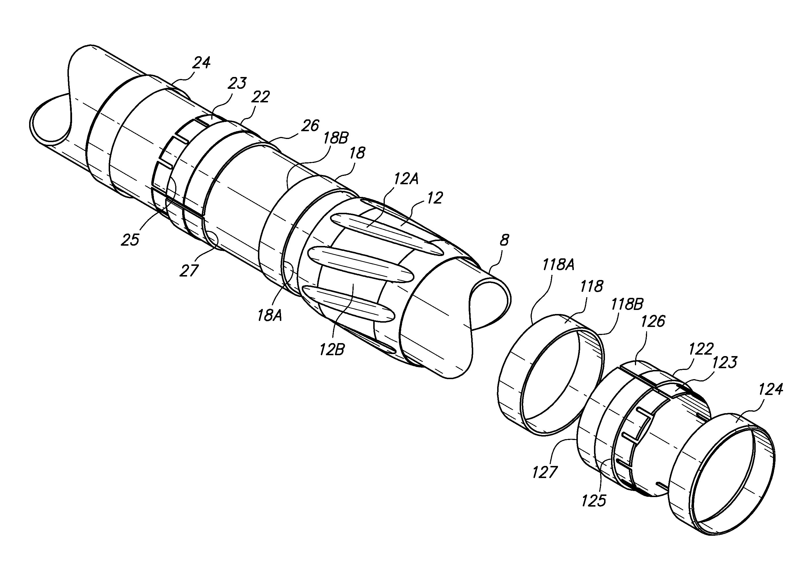
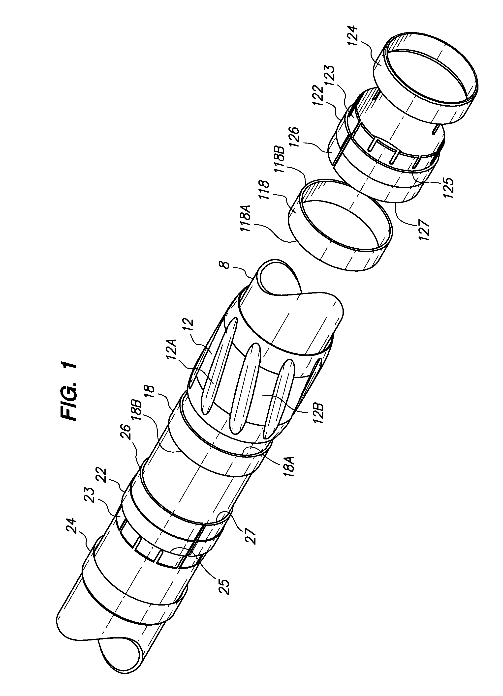
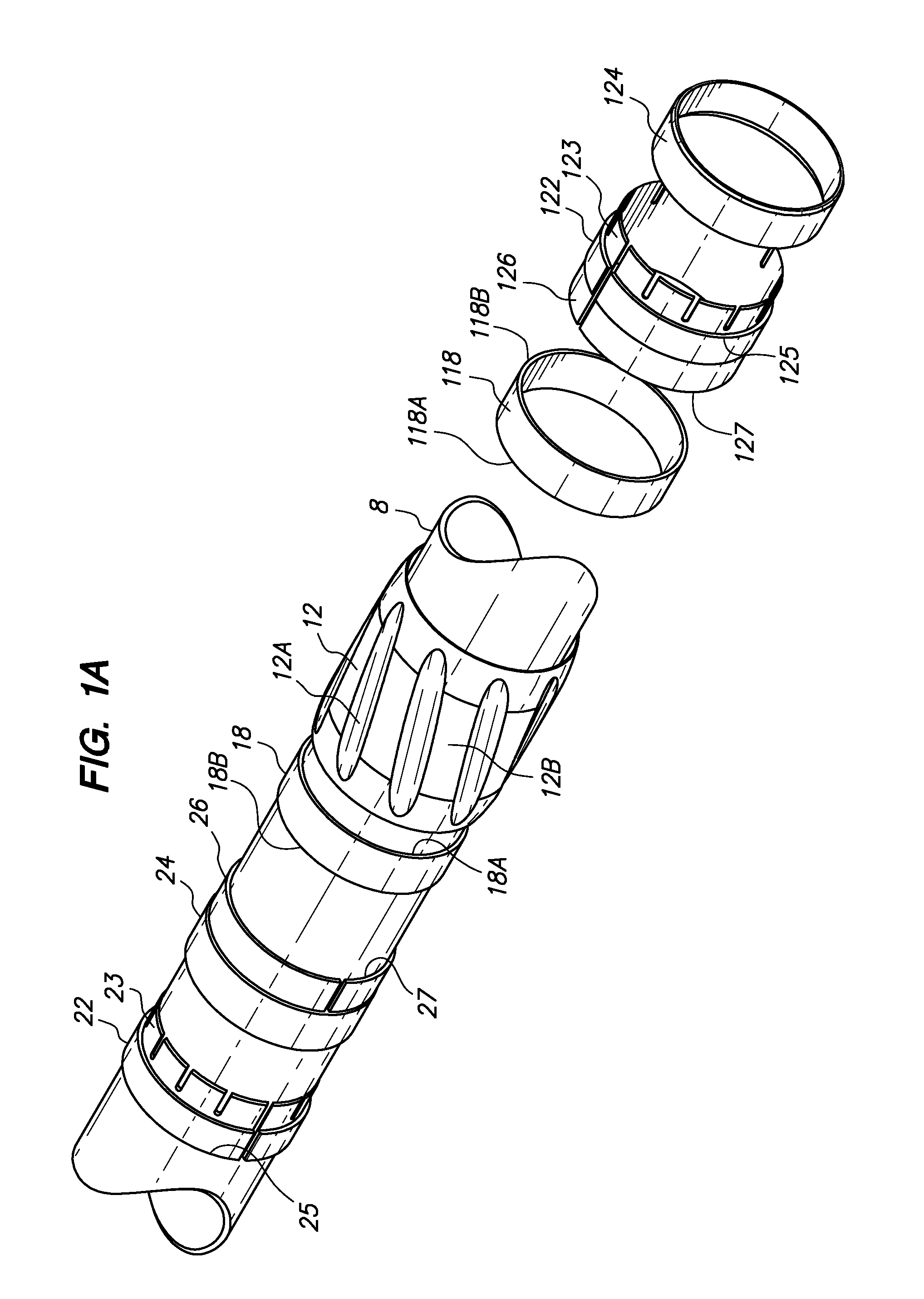
[0043]FIG. 1 is an exploded perspective view of an embodiment of a wear band and a tubular on which the wear band may be assembled. The components of the wear band of FIG. 1 are arranged aligned with or received on a tubular 8 in a sequence that facilitates assembly of the components into the wear band discussed below.

[0044]The embodiment of the wear band of FIG. 1 includes a rotating element 12 (e.g., sleeve) having a plurality of optional fluid channels 12A in the radially outwardly disposed wear surface 12B, a first sleeve bearing 18 and a second sleeve bearing 118, a first stop collar 22, having a plurality of fingers 23 extending in a first direction, and a second stop collar 122, having a plurality of fingers 123 extending in a second direction opposite the first direction. The depicted first stop collar 23 further includes a first sleeve 24, a stop wall 25 and a bearing spacer 26 extending in the second direction and terminating at a bearing face 27, and the depicted second s...


PUM


Abstract

In one embodiment, a wear band comprises a rotating element having a bore receivable on a tubular, the bore comprising first and second bore portions slidably receiving first and second sleeve bearings. Outer surfaces of the sleeve bearings slidably engage the bore portions and the bores of the sleeve bearings slidably engage the tubular. A first and a second stop collars may be received on the tubular to together straddle the rotating element and sleeve bearings to longitudinally secure the rotating element in a position on the tubular. The tubular may be included within a tubular string run into a borehole or into the bore of an installed casing, such as in casing while drilling. The rotating element provides stand-off between a tubular and the wall of a bore, reduces frictional resistance to longitudinal sliding and also to rotation of the tubular string within the bore.

Description

STATEMENT OF RELATED APPLICATIONS[0001]This application depends from and claims priority to U.S. Provisional Application Ser. No. 61 / 287,665 filed on Dec. 17, 2009, U.S. Provisional Application No. 61 / 237,202 filed on Aug. 26, 2009, U.S. Provisional Application No. 61 / 221,716 filed on Jun. 30, 2009, and U.S. Provisional Application No. 61 / 167,482 filed on Apr. 7, 2009.BACKGROUND OF THE INVENTION[0002]1. Field of the Invention[0003]This application relates to drilling and casing of earthen boreholes. Specifically, this application relates to a wear band for a tubular and a method of coupling a wear band to a tubular to be run into an earthen borehole. More specifically, this application relates to a friction-reducing wear band.[0004]2. Brief Description of the Related Art[0005]Earthen boreholes may be drilled using a tubular string, e.g., a drill string, to rotate a drill bit against the end of a borehole to remove material and extend the borehole. A drill string includes threadably ...

Claims


Application Information

Patent Timeline
Patent Type & Authority Applications(United States)
IPC IPC(8): E21B17/10E21B19/16E21B19/00
CPCE21B17/1085E21B17/1064E21B17/1028E21B17/1078E21B17/04E21B17/16
Inventor BUYTAERT, JEANMILLER, EUGENE EDWARDHINING, IRA EUGENE
Owner INNOVEX DOWNHOLE SOLUTIONS INC
Why Eureka
Try Eureka