
Active vibration isolation system

a technology of active vibration isolation and vibration compensation, which is applied in the direction of machine supports, domestic objects, applications, etc., can solve the problems of system redundancy, increased demands on a system for vibration isolation or vibration compensation, and the “permanent” provision of the required force by the used actuators

Active Publication Date: 2011-03-17
INTEGRATED DYNAMICS ENG
View PDF2 Cites 23 Cited by
  • Summary
  • Abstract
  • Description
  • Claims
  • Application Information

AI Technical Summary

Benefits of technology

[0060]Generally the invention is described by vibration isolation systems with pneumatic isolators wherein the pneumatic isolators are intended to be used not only for position bearing but for vibration or force compensation as well. The application of the pneumatic system as an additional force-actuator-system enables the possibility to generate larger forces for compensation. Additionally, waste heat, for instance caused by high currents of the lorentz-motors, which act often as first actuators, can be reduced.
[0063]Preferably, all isolators of the system, which particularly each comprises a controllable valve system, are applied in the controlling. For example, a system with four isolators can be operated with four controllable valves and not only with three controllable valves. Since the redundancy causes no problems in the controlling.

Problems solved by technology

The system is redundant.
Since the stages own a quite high weight, increased demands are required to a system for vibration isolation or vibration compensation.
In particular the “permanent” providing of the required force by the used actuators proves to be problematic.

Method used


Image

  • Active vibration isolation system
  • Active vibration isolation system
  • Active vibration isolation system

Examples


Embodiment Construction

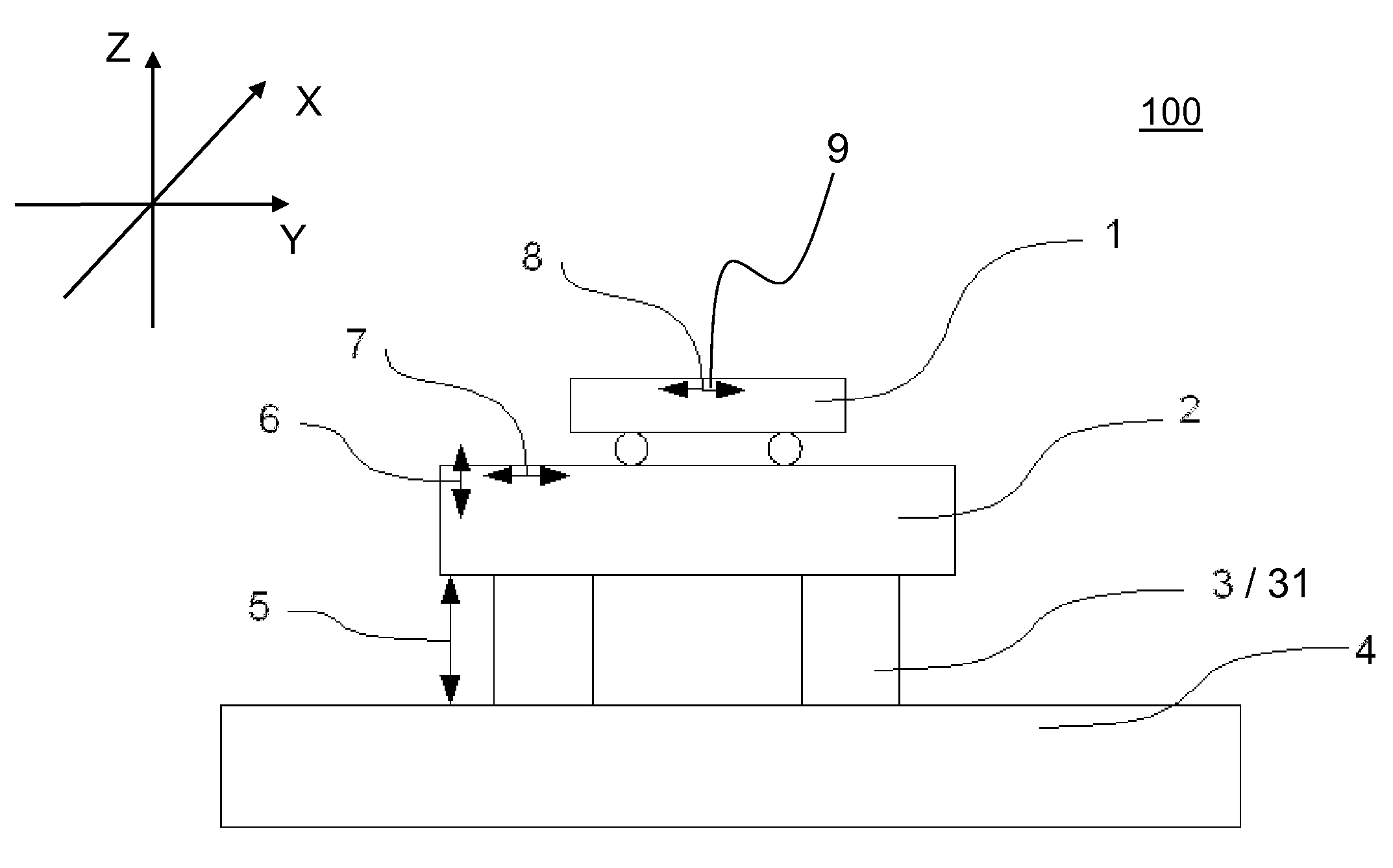
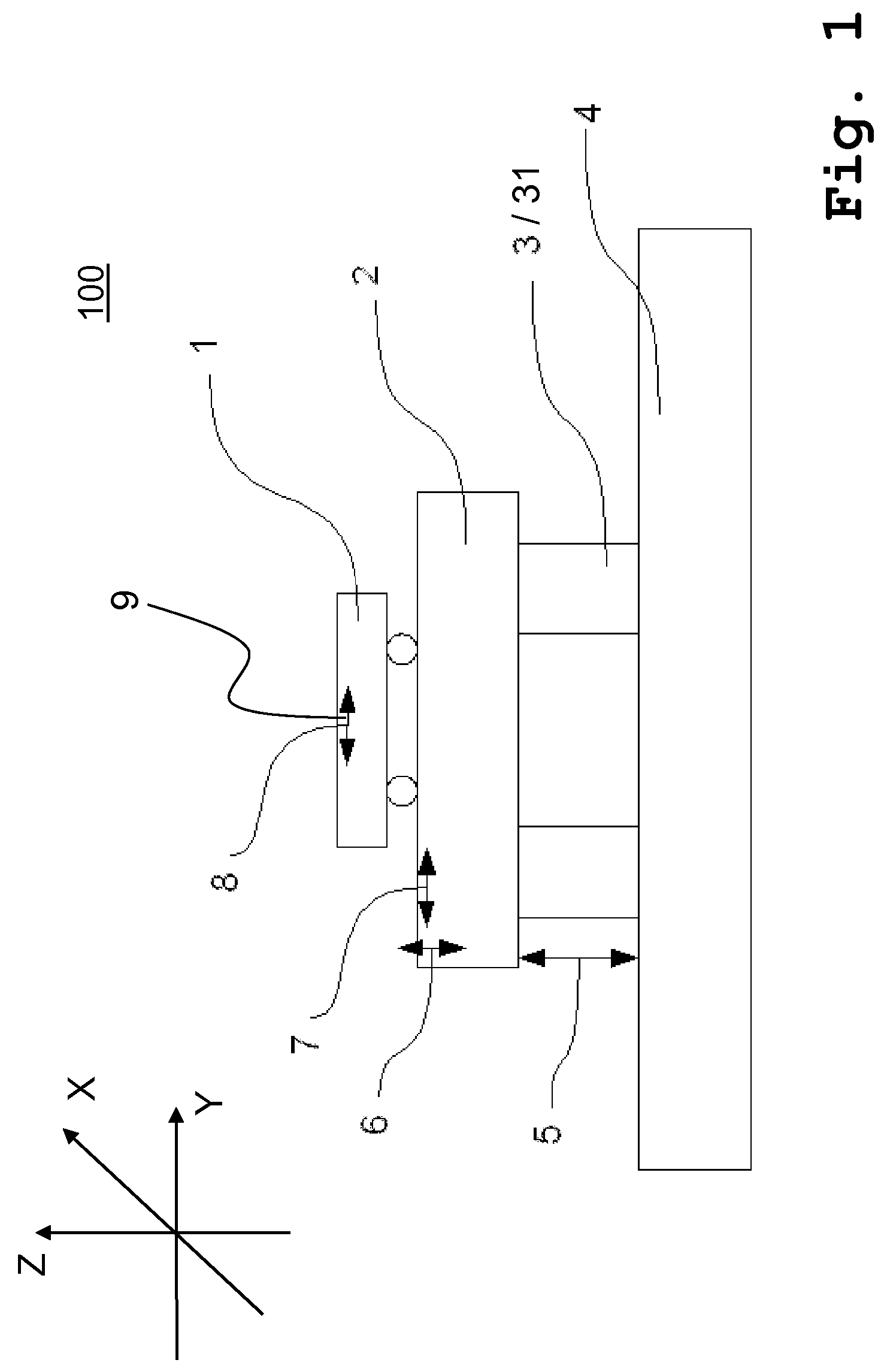
[0076]FIG. 1 shows a vibration isolation system 100 based on pneumatic isolators 3. A body 2 which is to be isolated is carried or borne by means of pneumatic isolators 3 and is therefore isolated from vibrators or isolated from a floor 4. A movable table 1, in particular for the transportation of wafers, lithography-devices, waver-handling-systems and / or microscopes, is positioned upon the body 2.

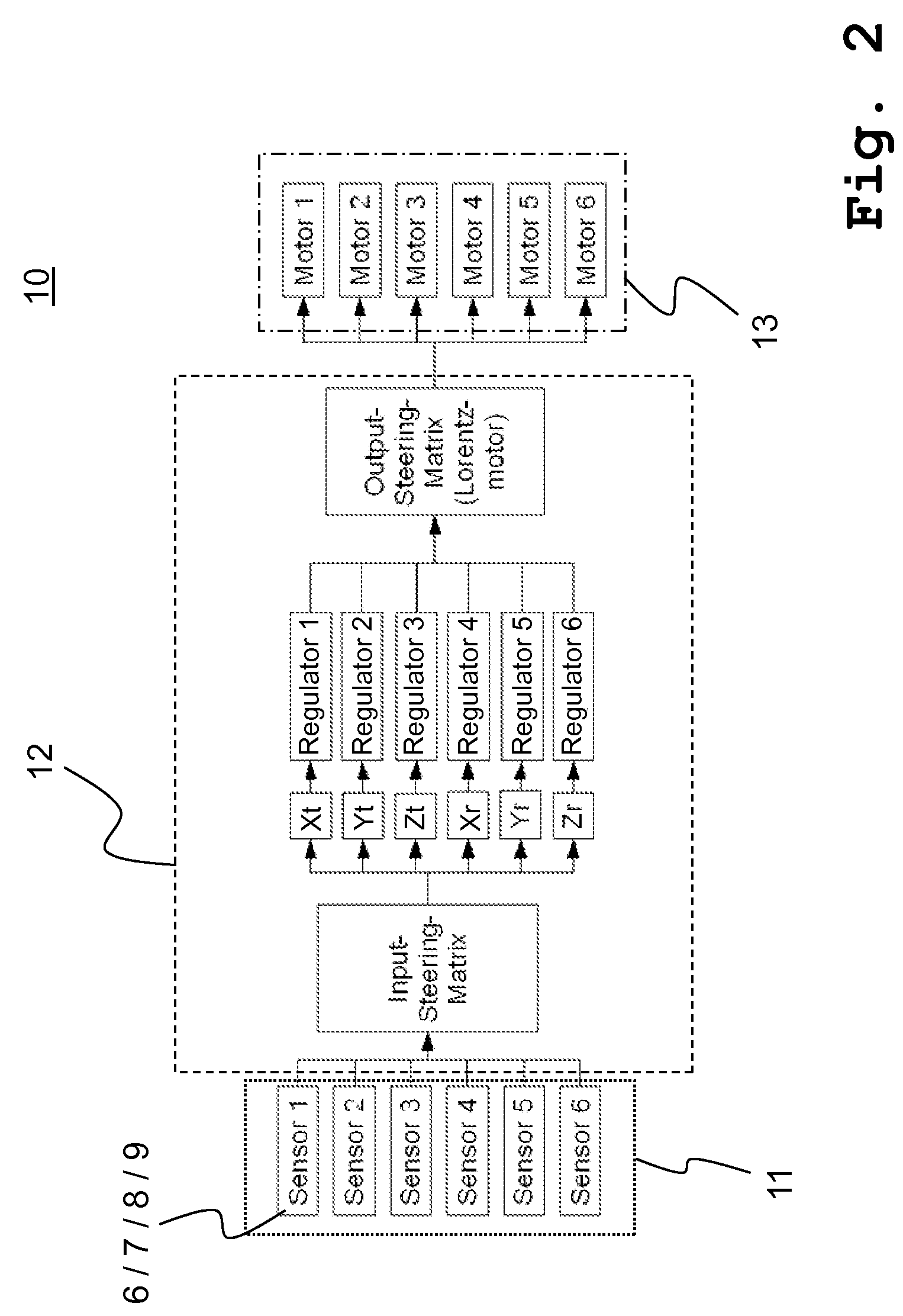
[0077]For active vibration isolation the system 100 comprises in one embodiment four pneumatic isolators 3, a plurality of actors and a plurality of sensors 5, 6, 7, 8 and 9 as vibration signal transducers. By means of the sensors 6, 7, 8 and 9 vibrations or generally motions of the support body 2 and the load 1 which is to be isolated can be detected, processed into signals and transferred to a controlling or regulating system, as for instance the first regulating 10. Accordingly, the sensors 5, 6, 7, 8 and 9, acting as vibration signal transducers, provide sensor signals which represent ...


PUM


Abstract

The present invention relates to a method for regulating an active vibration isolation system and to an active vibration isolation system, in particular for a vibration isolated positioning of lithography-devices, wafer-handling-systems and / or microscopes, as for instance scanning microscopes. The active vibration isolation system comprises the following components: a support body for bearing a load which is to be isolated; pneumatic vibration isolators with controllable valves for carrying the support body with respect to the ground; position sensors for providing vertical position signals of the support body; a first regulating system for vibration compensation in at least one degree of freedom in translation (Xt,Yt,Zt) and in at least one degree of freedom in rotation (Xr,Yr,Zr) and a second pneumatic regulating system for vibration compensation in at least one degree of freedom selected from three degrees of freedom (Zt,Xr,Yr) which are effective in vertical direction.

Description

CROSS-REFERENCE TO RELATED APPLICATIONS[0001]European patent application EP 09 011 638.5, filed Sep. 11, 2009, is incorporated herein by reference.FIELD OF THE INVENTION[0002]The present invention relates to a method for regulating an active vibration isolation system and to an active vibration isolation system, in particular for a vibration isolated positioning of lithography-devices, wafer-handling-systems and / or microscopes, as for instance scanning microscopes.BACKGROUND OF THE INVENTION[0003]Vibration isolation systems are known and are required in several technique areas, as for instance in the area of semiconductor industry. For instance document DE 69817750 T2 shows a vibration isolation system which is particularly provided for a vibration isolated positioning of a lithography-device. It is shown a load which is positioned on air bearings to isolate the load from vibrations and / or oscillations. Typically the load comprises a table and components which are positioned on the ...

Claims


Application Information

Patent Timeline
IPC IPC(8): F16F15/16
CPCF16F15/027
Inventor HEILAND, PETER
Owner INTEGRATED DYNAMICS ENG
Learn More