Method and apparatus for sending and receiving multicast packets

Active Publication Date: 2011-03-17
ALCATEL LUCENT SAS
View PDF9 Cites 40 Cited by
  • Summary
  • Abstract
  • Description
  • Claims
  • Application Information

AI Technical Summary

Benefits of technology

[0018]With the solution of sending a multicast packet for a subscriber terminal as provided in the present invent

Problems solved by technology

The above UP-MC solutions waste much network

Method used


Image

  • Method and apparatus for sending and receiving multicast packets
  • Method and apparatus for sending and receiving multicast packets
  • Method and apparatus for sending and receiving multicast packets

Examples


Embodiment Construction

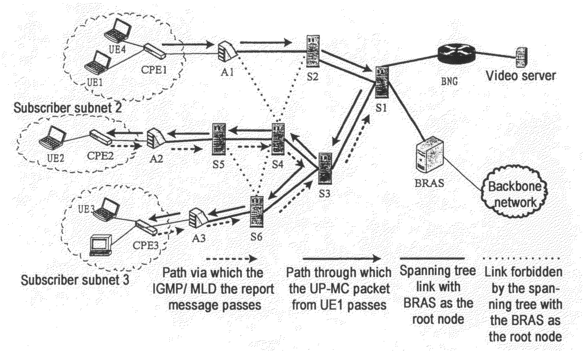
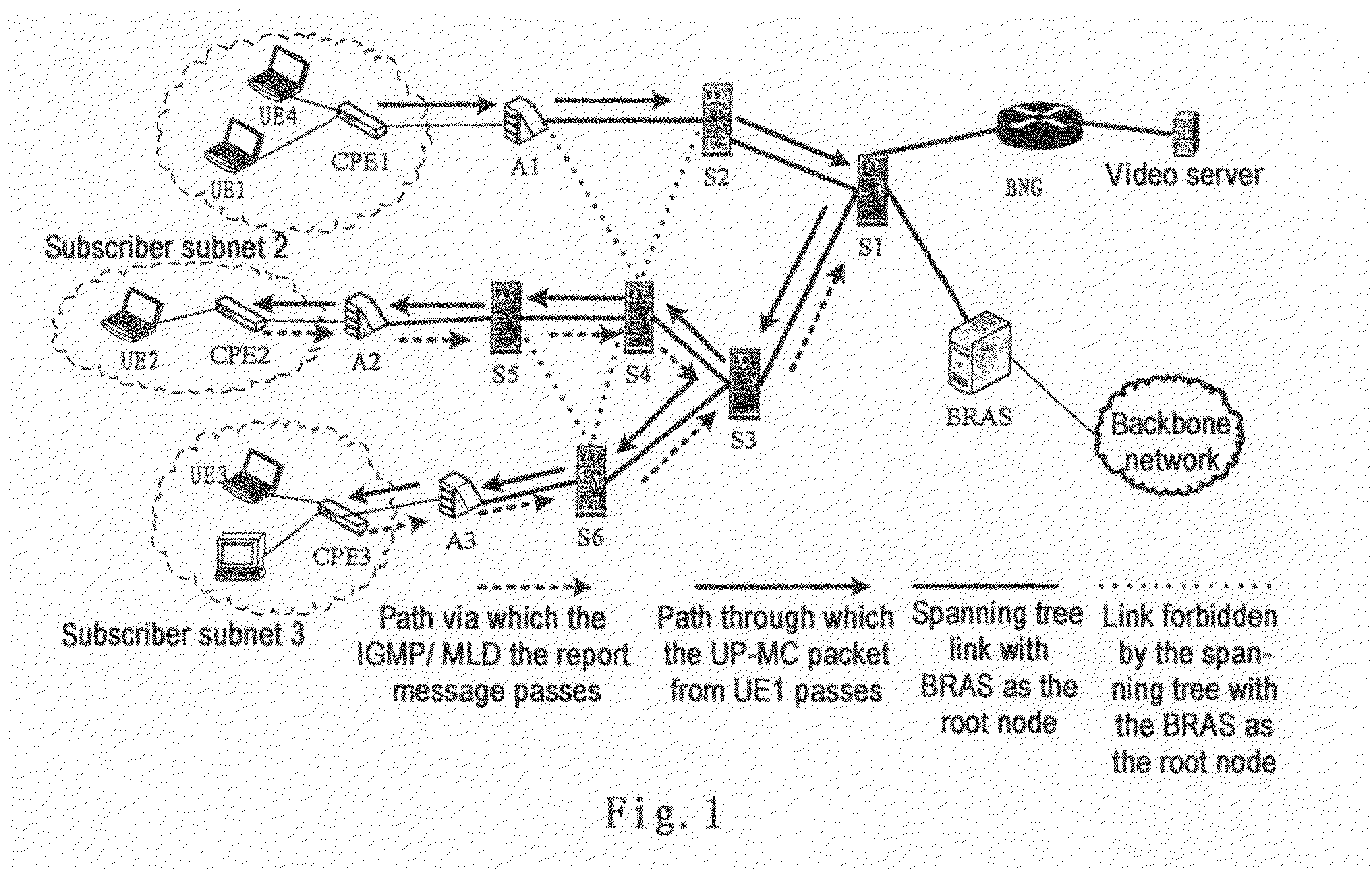
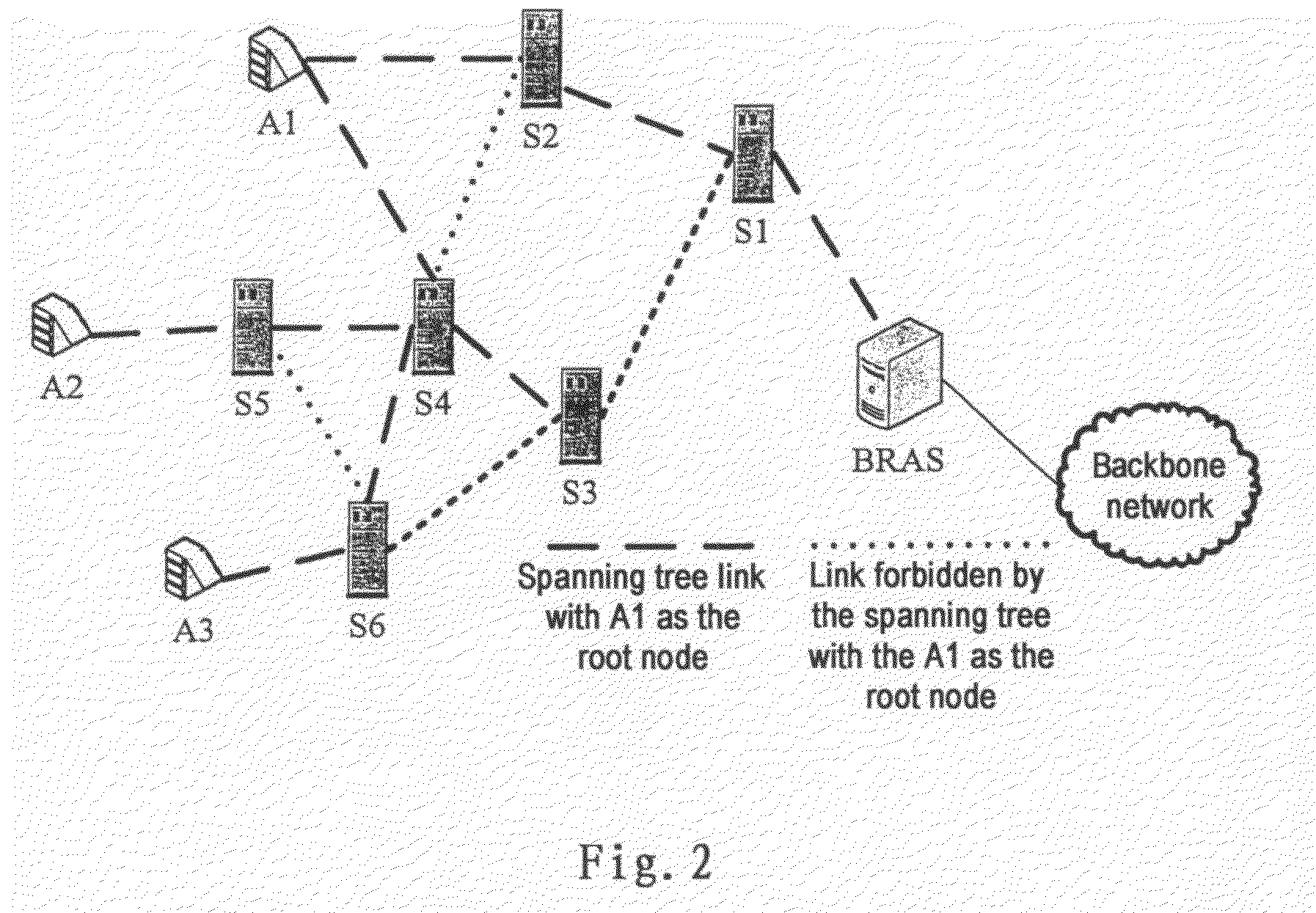
[0039]The basic principle of the present invention is that a network device takes itself as a root node to generate a logical topology tree for a subscriber terminal that requests to send a multicast packet, and then generate a multicast tree on the logical topology tree with the network device itself as the root node, to thereby forward the multicast packet. The concept “logical topology tree” here refers to a tree topological structure which takes the network device as a root node and is connected to each other network device in a network where the network device is located. A topology path of the multicast tree, which is established on the logical topology tree, is a subset of the topology path of the logical topology tree.

[0040]For the network topology structure shown in FIG. 1, when the subscriber terminal UE1 accessed to the network via the access device A1 needs sending the multicast packet, a logical topology tree is generated with the access device A1 as the root node, and ...


PUM


Abstract

The present invention relates to a solution for taking a network equipment in a communication network as a root node to generate a logical topology tree for a subscriber terminal which requests the sending of multicast packets, and then generating a multicast tree on the logical topology tree with the network device as the root node, so as to forward the multicast packets. With the solution of sending a multicast packet to the subscriber terminal, it can effectively save the network bandwidth resource and reduce the transmission delay of multicast packet.

Description

TECHNICAL FIELDS[0001]The present application relates to a communication network, and in particular relates to a method and apparatus for sending and receiving multicast packets in a communication network.BACKGROUND ART[0002]In an access network, multicast (MC) technology has been widely used to deliver multicast service flows (e.g., a multicast service in an interactive network Television (IPTV)) from an operator side to subscriber networks. Upstream MC (i.e. multicast data from the subscriber subnet) is not allowed. The access device just discards the multicast data from the subscriber networks. However, the multicast in the subscriber networks is sure to exist. For example, a user in the subscriber networks intends to multicast his / her existing video or live performance to his / her friends and relatives; or the headquarters multicast a CEO's speech to his branches. On the other hand, network operators would like to provide more value-added services to attract more subscribers to t...

Claims


Application Information

Patent Timeline
IPC IPC(8): H04L12/56H04L45/02H04L45/16
CPCH04L12/18H04L12/2861H04L12/4641H04L45/48H04L45/04H04L45/16H04L45/02H04L45/484H04L45/488H04L12/28
Inventor WEN, HAIBO
Owner ALCATEL LUCENT SAS
Why Eureka
Try Eureka