Cooling device for molding apparatus

a technology of cooling device and molding machine, which is applied in the field of cooling device for molding apparatus, can solve the problems of ineffective cooling device employed in the thermoforming machine to effectively and uniformly cool the di

Inactive Publication Date: 2011-03-17
HON HAI PRECISION IND CO LTD
View PDF7 Cites 6 Cited by
  • Summary
  • Abstract
  • Description
  • Claims
  • Application Information

AI Technical Summary

Benefits of technology

[0005]Therefore it is desirable to provide a cooling device which can cool the molding apparatus more effectively and uniformly.

Problems solved by technology

The cooling device employed in the thermoforming machine is ineffective to cool the die effectively and uniformly because of all of the surfaces of the die which are away from the conduits and which mostly cannot be cooled by the fluid inside the conduits.

Method used


Image

  • Cooling device for molding apparatus
  • Cooling device for molding apparatus
  • Cooling device for molding apparatus

Examples


Embodiment Construction

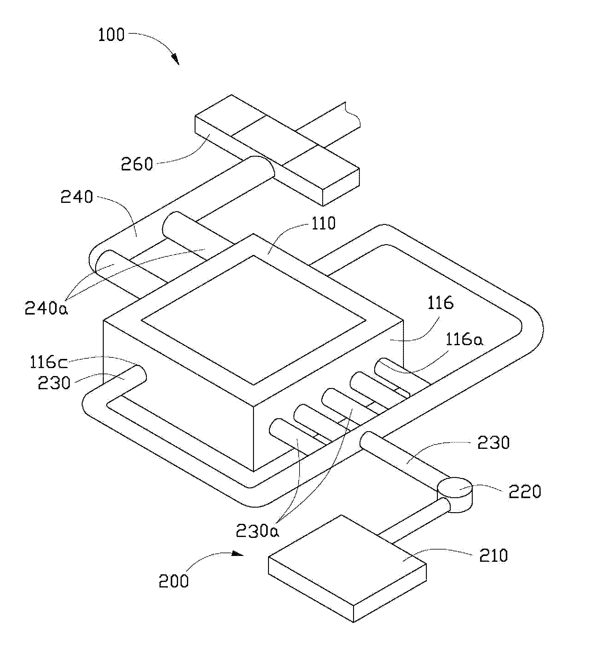
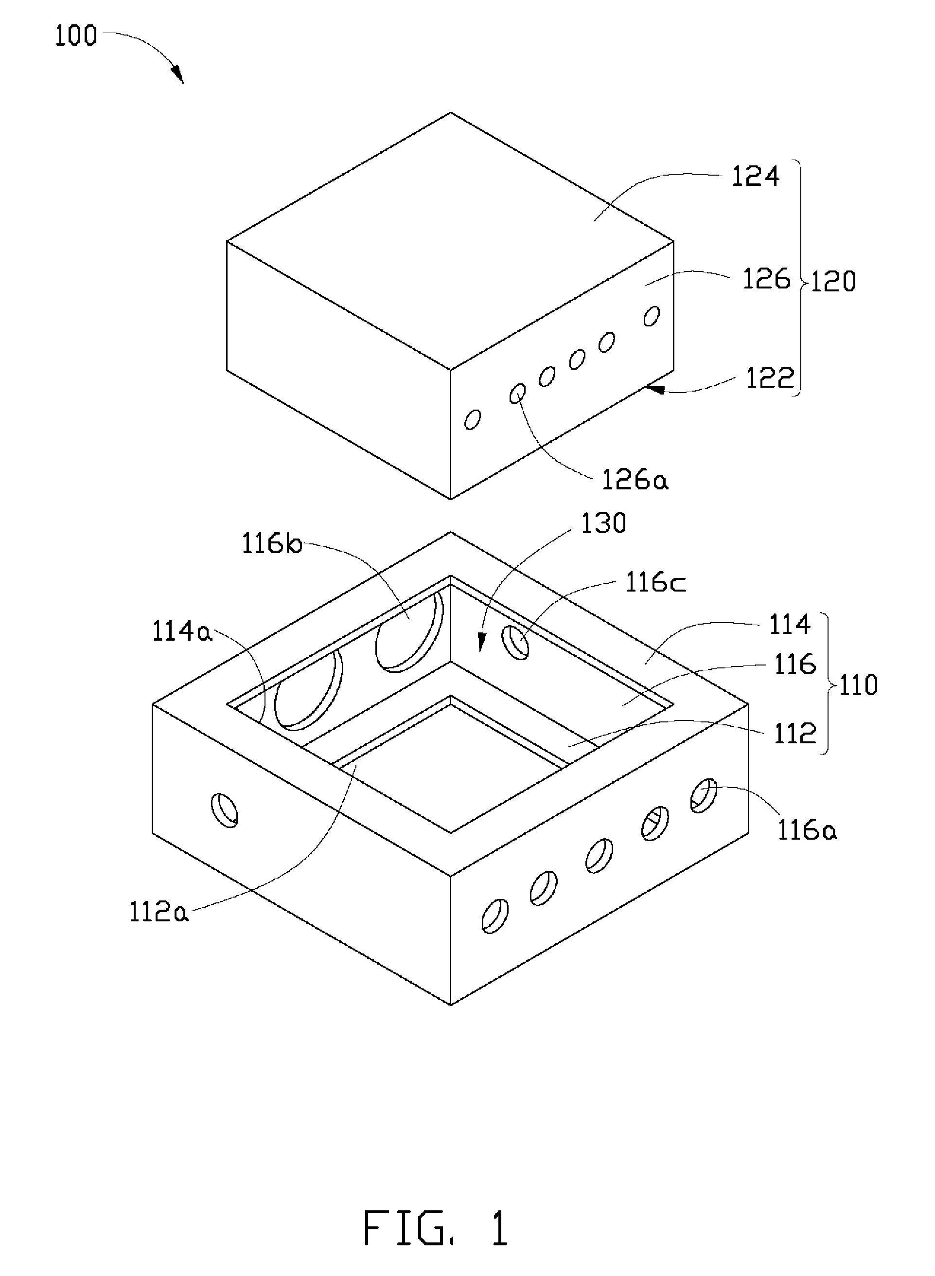
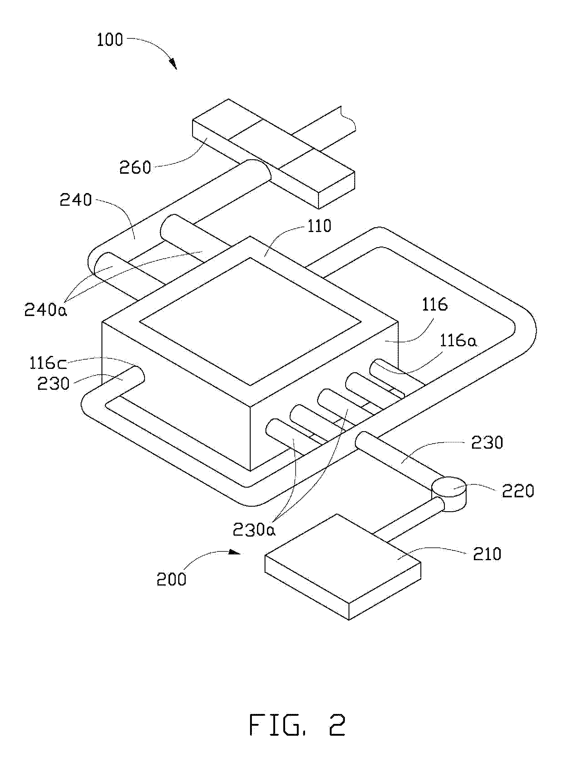
[0008]Referring to FIG. 1, a cooling device 100 for cooling a molding apparatus is shown. The cooling device 100 includes a housing 110 and a die 120 received in the housing 110.

[0009]The housing 110 is shaped corresponding to the shape and profile of the die 120, and includes a bottom 112, a top 114 and a plurality of sidewalls 116 interconnecting the bottom 112 and the top 114. The bottom 112 defines a first opening 112a through which the die 120 is exposed. The length and the width of the first opening 112a are shorter than the respective counterparts of the corresponding sides of the die 120, and are sealed by the die 120 from the inner side of the bottom 112. The top 114 defines a second opening 114a therein corresponding to the first opening 112a. The second opening 114a serves as the entrance for inserting the die 120 into the housing 110. One of the sidewalls 116 defines a number of first inlets 116a for the passage of water into the housing 110. Two outlets 116b are defined...


PUM

PropertyMeasurementUnit
diametersaaaaaaaaaa
shapeaaaaaaaaaa
lengthaaaaaaaaaa

Abstract

A cooling device includes a housing and a die. The housing includes a top, a bottom, and a plurality of sidewalls interconnecting the bottom and the top. Two opposite sidewalls of the housing respectively defines a plurality of first inlets and outlets. The die is received in the housing and defines a plurality of first passages spanning opposite side surfaces, and the first passages are aligned with the first inlets and the outlets of the housing. A second passage is defined between the die and the sidewalls of the housing. The first and second passages are configured for conducting the cooling fluid to cool the die.

Description

BACKGROUND[0001]1. Technical Field[0002]The disclosure relates to cooling devices for molding apparatuses.[0003]2. Description of Related Art[0004]Generally, for molding thermoplastic using a thermoforming machine, such as an injection-molding machine or apparatus, the following steps are carried out. First, the thermoplastic to be molded is supplied to a thermoforming machine; the thermoplastic to be plasticized, is heated in a cylindric chamber in the machine, and then the melted plastic is injected into a die from a nozzle. Finally, the molded plastic inside the die is cooled by the conducting of cooling fluid into a plurality of conduits formed in the die. The cooling device employed in the thermoforming machine is ineffective to cool the die effectively and uniformly because of all of the surfaces of the die which are away from the conduits and which mostly cannot be cooled by the fluid inside the conduits.[0005]Therefore it is desirable to provide a cooling device which can co...

Claims


Application Information

Patent Timeline
Patent Type & Authority Applications(United States)
IPC IPC(8): B29C45/73
CPCB29C45/7312
Inventor CHEN, HSIANG-HUNG
Owner HON HAI PRECISION IND CO LTD
Why Eureka
Try Eureka