
Method and device for lubricating and cooling a bearing that is subject to high loads

a technology of high load and bearing, applied in the direction of bearing cooling, sliding contact bearing, crankshaft, etc., can solve the problems of temperature increase in the bearing, adversely affecting the geometry of the bearing and therefore the bearing accuracy, adversely affecting the quality of the lubricant and therefore the lubricating action, etc., to achieve effective and uniform cooling of the bearing

Inactive Publication Date: 2015-11-10
SCHAEFFLER TECH AG & CO KG
View PDF15 Cites 1 Cited by
  • Summary
  • Abstract
  • Description
  • Claims
  • Application Information

AI Technical Summary

Benefits of technology

This approach provides uniform and effective cooling of the bearing without additional hydraulic losses, maintaining low temperature differences and improving bearing efficiency by utilizing the gas's ability to absorb heat and act as a lubricant.

Problems solved by technology

At high rotational speeds of bearings, heat is generated as a result of the friction, which heat leads to a temperature increase in the bearing.
The increased bearing temperature generally adversely affects the geometry of the bearing and therefore the bearing accuracy, and in addition, said increased bearing temperature also adversely affects the quality of the lubricant and therefore the lubricating action.
The first measure is constructively and structurally complex and expensive, and leads in general to high temperature differences in the bearing, with the risk of the bearing being damaged.
The latter measure possibly entails high hydraulic losses in the bearing, so that the drive power must be correspondingly increased, resulting in the efficiency being impaired.
Said arrangement, however, has the disadvantage that the lubricant heats up to its end temperature while still in the bearing region, so that there are relatively high temperature differences between the region in which the lubricant is supplied to the bearing arrangement and the region in which the lubricant leaves the bearing arrangement, and the bearing geometry is therefore still adversely affected.
Furthermore, the required quantity of lubricant is very high, so that high hydraulic losses occur in the bearing, and the efficiency of said bearing is reduced.

Method used


Image

  • Method and device for lubricating and cooling a bearing that is subject to high loads
  • Method and device for lubricating and cooling a bearing that is subject to high loads
  • Method and device for lubricating and cooling a bearing that is subject to high loads

Examples


Embodiment Construction

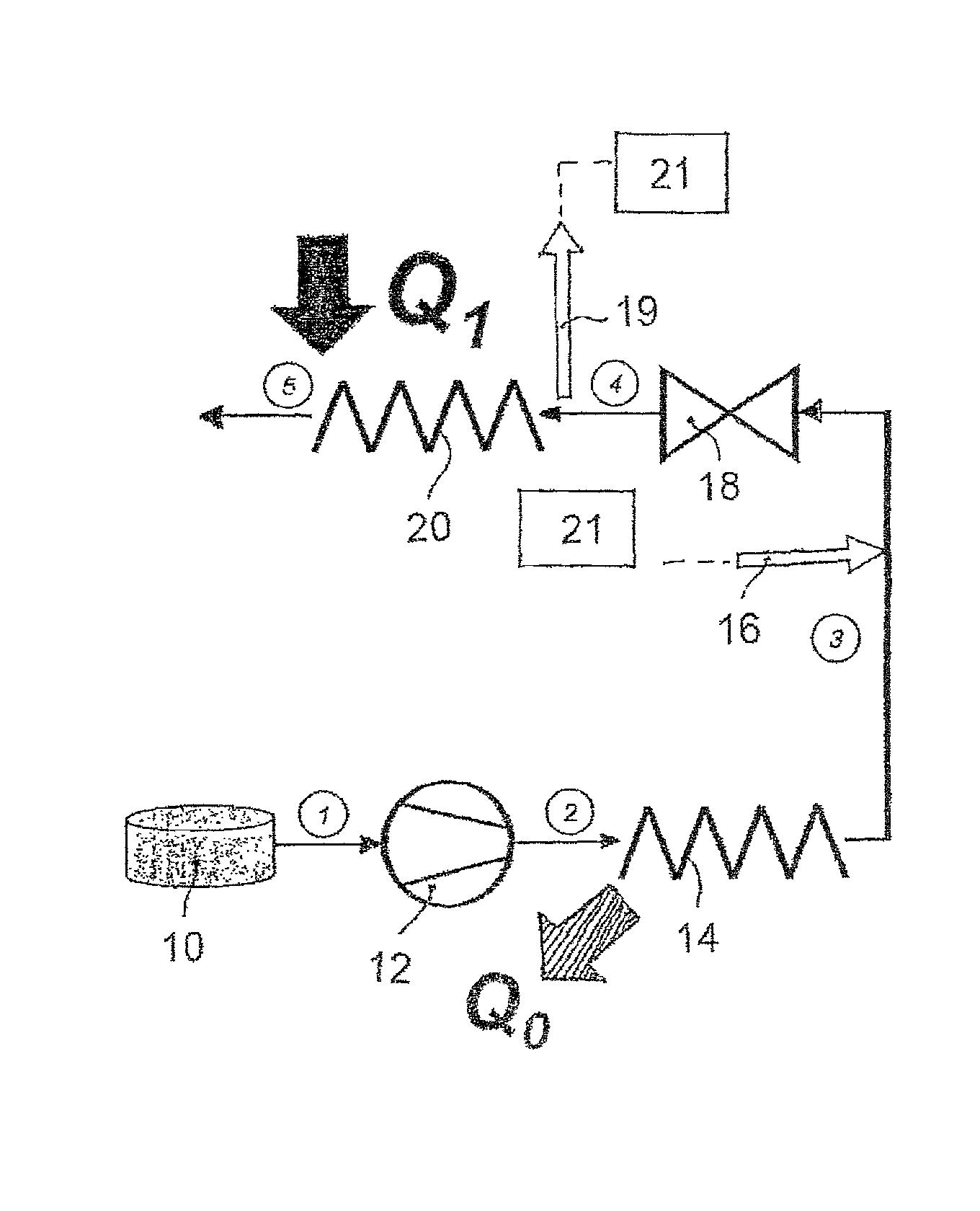
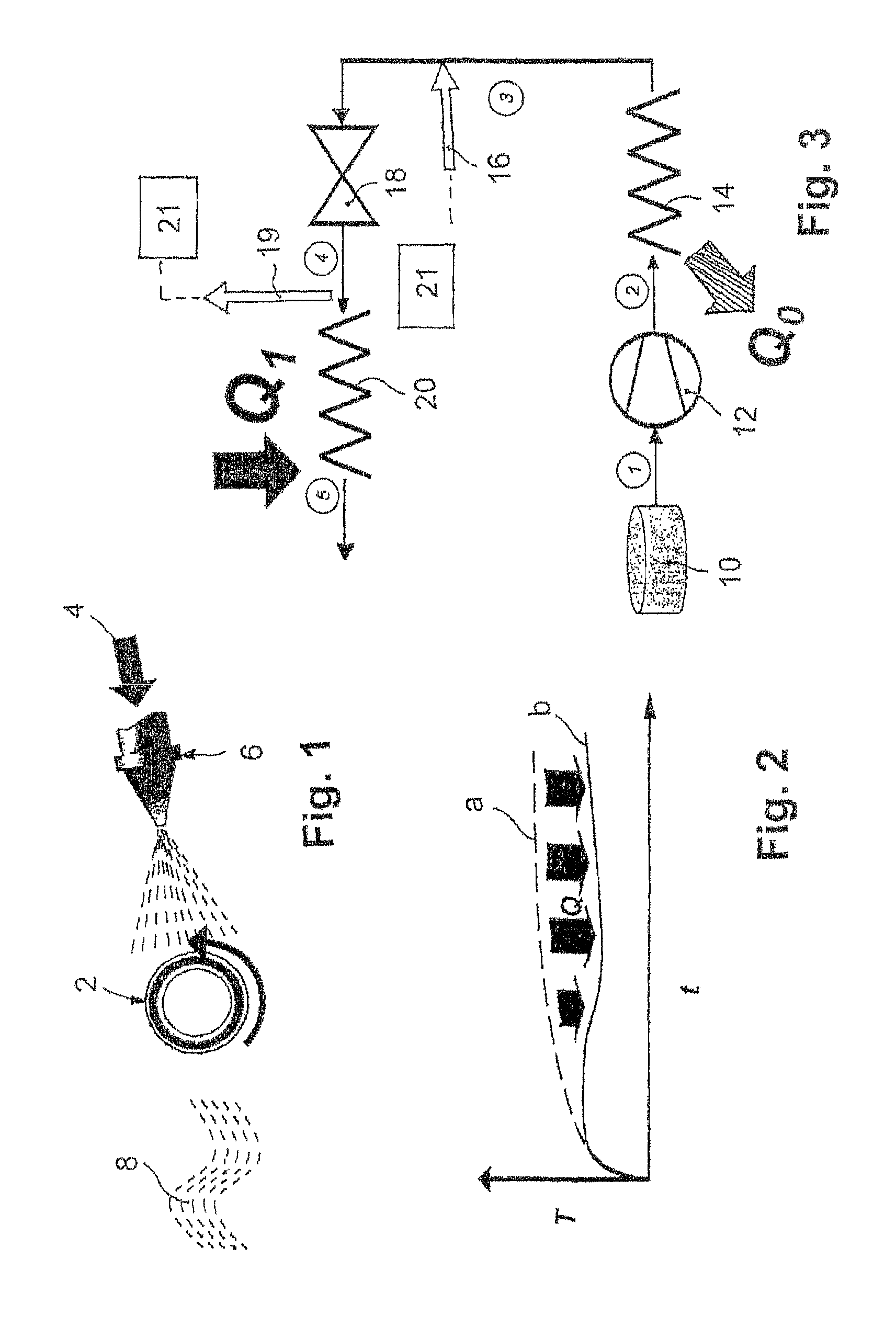
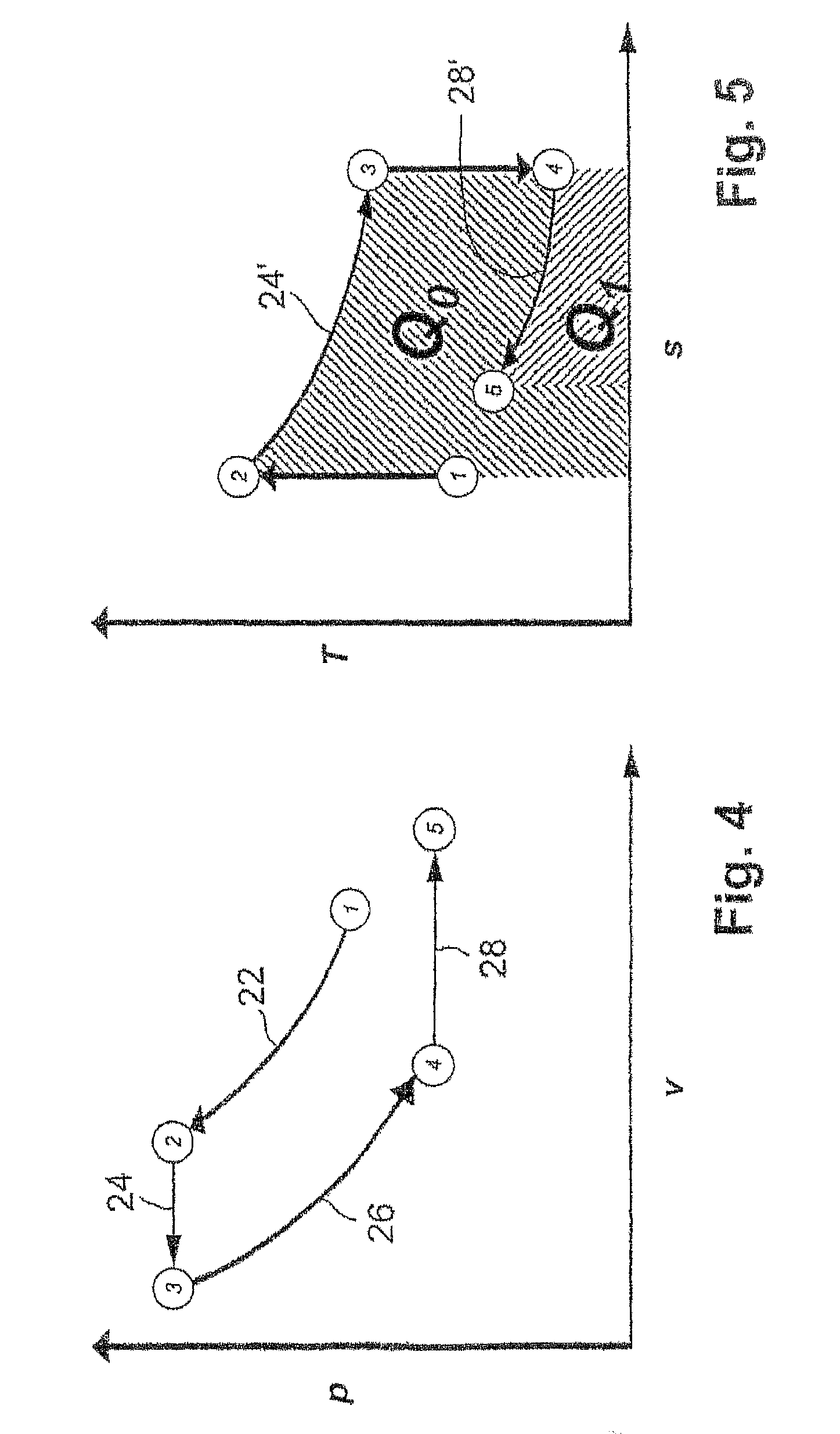
[0006]The invention is based on the knowledge that, utilizing a typical property of supercritical or hypercritical gases, specifically that of being able to dissolve other media such as for example lubricants, it should possible to effect a heat transfer from the bearing to the gas directly and from the lubricant to the gas already in the region of the bearing and not only downstream of the bearing, in order to thereby ensure effective and uniform cooling of the entire bearing without additional lubricant quantities.

[0007]According to the features of claim 1, the invention proceeds from a method and a device for lubricating and cooling a highly-loaded bearing, in particular a fast-running and / or thermally-loaded bearing, in which a lubricant and a gas are mixed in order to cool the bearing.

[0008]The method according to the present invention provides the following method steps:[0009]a) A gas is placed into a supercritical state.[0010]b) A lubricant is dissolved in the supercritical g...


PUM


Abstract

The invention relates to a method for lubricating and cooling a bearing that is subject to high loads and to a device for carrying out said method. The invention is characterized by dissolving a lubricant in a supercritical gas that is cooled down to a low temperature and feeding the gas / lubricant mixture to the baring. The gas / lubricant mixture is relaxed in the bearing area, thereby releasing the lubricant and lubricating the bearing. The now subcritical gas that is cooled down to a low temperature is used for cooling and is discharged to the exterior. The gas used is carbon dioxide (CO2) and the lubricant is a hydrocarbon-based lubricant.

Description

FIELD OF THE INVENTION[0001]The invention relates to a method for lubricating and cooling a highly-loaded bearing, in particular a fast-running and / or thermally-loaded bearing, with a lubricant and a gas being mixed, and to a device for carrying out said method.BACKGROUND OF THE INVENTION[0002]Highly-loaded bearings of the above-described type serve for example for mounting motor spindles in machine tools, compressor and turbine shafts in gas turbines, transmission shafts in fast-running transmissions etc. At high rotational speeds of bearings, heat is generated as a result of the friction, which heat leads to a temperature increase in the bearing. The increased bearing temperature generally adversely affects the geometry of the bearing and therefore the bearing accuracy, and in addition, said increased bearing temperature also adversely affects the quality of the lubricant and therefore the lubricating action. In order to avoid said disadvantages, various measures are already known...

Claims


Application Information

Patent Timeline
Patent Type & Authority Patents(United States)
IPC IPC(8): F16N1/00F16N7/32F16C33/66F16C21/00F16C43/00F16C37/00F16C17/00
CPCF16C37/007F16C33/6662F16C33/6688F16N7/32
Inventor BAYER, OSWALDSCHELLBERG, OLIVER
Owner SCHAEFFLER TECH AG & CO KG
Learn More