Fuel cell provided with a temperature-control system and method for thermal control of the cell

a technology of temperature control system and fuel cell, which is applied in the direction of fuel cell control, fuel cell details, electric generators, etc., can solve the problems of increasing the overall consuming energy, significant increase in the weight and the size of the cell, and reducing the size of the fuel cell, so as to maximize the heat exchange area, reduce the size, and simplify the fabrication of the fuel cell

Active Publication Date: 2018-09-06
SAFRAN POWER UNITS
View PDF3 Cites 4 Cited by
  • Summary
  • Abstract
  • Description
  • Claims
  • Application Information

AI Technical Summary

Benefits of technology

[0013]By incorporating a heating element in the condensation zone of the two-phase thermal diffuser, the functions of cooling and heating the fuel cell are combined in the two-phase thermal diffuser, thereby simplifying fabrication of the fuel cell and reducing its size. Specifically, there is no longer any need to provide within the fuel cell both a cooling system and a heating system that is distinct from the cooling system.
[0014]Furthermore, the arrangement of the evaporation zone of the two-phase thermal diffuser between two adjacent unit cells enables the fuel cell to be heated or cooled in a manner that is more uniform and more effective than, for example, when the fuel cell is heated by heating resistances arranged at each end of the fuel cell. Specifically, the heat exchange area betw

Problems solved by technology

In known manner, the device for cooling the cell comprises a pump for circulating cooling liquid, thereby increasing the overall size of the fuel cell and consuming energy.
It can thus be understood that the preheating of the cell is not uniform within the stack.
Although

Method used


Image

  • Fuel cell provided with a temperature-control system and method for thermal control of the cell
  • Fuel cell provided with a temperature-control system and method for thermal control of the cell
  • Fuel cell provided with a temperature-control system and method for thermal control of the cell

Examples


Embodiment Construction

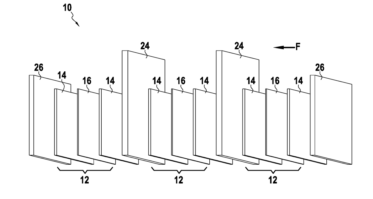
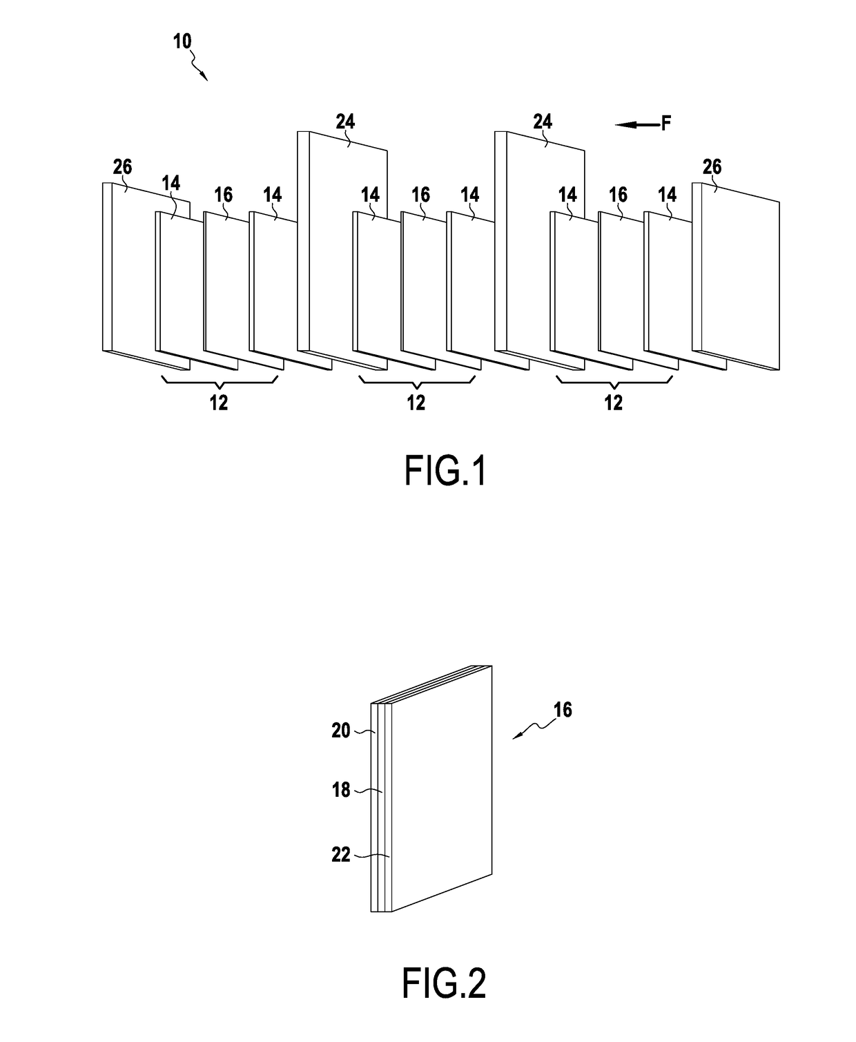
[0038]FIG. 1 is an exploded diagrammatic view of a fuel cell 10. The fuel cell 10 comprises three unit cells 12, each comprising two bipolar plates 14 arranged on either side of a membrane electrode assembly 16. The membrane electrode assembly 16 shown in FIG. 2 comprises a proton exchange membrane 18 arranged between an anode 20 and a cathode 22. Each unit cell 12 is separated from the adjacent unit cell 12 by a two-phase thermal diffuser 24. Each two-phase thermal diffuser 24 is thus arranged between two bipolar plates 14 of two adjacent unit cells 12. The fuel cell 10 also has a current collector plate 26 at each of its ends.

[0039]It can be understood that in the fuel cell 10, the various elements shown in the exploded view are in contact with one another.

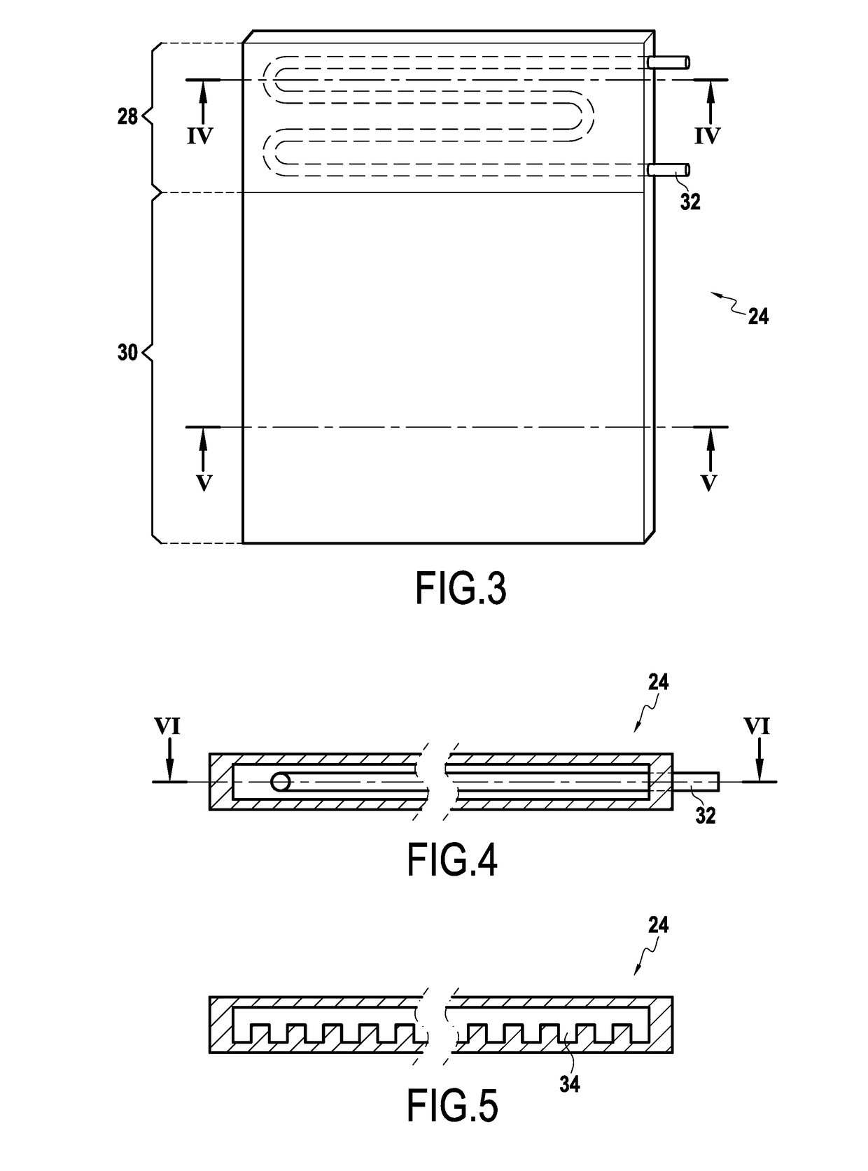
[0040]FIG. 3 shows a two-phase thermal diffuser 24 that has a condensation zone 28 and an evaporation zone 30 together with a heating element 32 arranged in the condensation zone 28. As shown in FIG. 1, the evaporation zone 30 i...


PUM


Abstract

The invention relates to a fuel cell (10) comprising a membrane electrode assembly (16) and two gas diffusion layers (14) co-operating with the assembly to form a unit cell (12). The fuel cell (10) also has a two-phase thermal diffuser (24) having a condensation zone and an evaporation zone, the evaporation zone being arranged between the bipolar plates (14) of two adjacent unit cells (12). The two-phase thermal diffuser (24) also has a heating element arranged in the condensation zone. The invention also provides a system comprising the fuel cell and a controller, and it also provides a method of regulating the temperature of the fuel cell.

Description

BACKGROUND OF THE INVENTION[0001]The present invention relates to a fuel cell including a system for regulating the temperature of the fuel cell, and in particular a proton exchange membrane cell.[0002]Fuel cells generally comprise a stack of unit cells arranged between two current collectors. Each unit cell is made up of a membrane electrode assembly made up of a proton exchange membrane arranged between an anode electrode and a cathode electrode, the assembly being arranged between two bipolar plates, the membrane electrode assembly is itself arranged between two distributor plates, also referred to as bipolar plates. When stacking unit cells, the distributor plates arranged between two membrane electrode assemblies allow hydrogen to flow over one of their faces and air over the opposite face, and they are also called bipolar plates.[0003]Each fuel cell has an optimum operating temperature that depends on the nature of the various components making up the cell. Thus, in order to g...

Claims


Application Information

Patent Timeline
IPC IPC(8): H01M8/04007H01M8/1004H01M8/0202H01M8/04701H01M8/043
CPCH01M8/043H01M8/04738H01M8/1004H01M8/04074H01M8/0202H01M8/0258H01M8/04059H01M8/04225H01M8/04731Y02E60/50H01M8/04037H01M8/04268
Inventor VERDIER, ANTOINEHORDE, THÉOPHILEBOUDJEMAA, FABIEN
Owner SAFRAN POWER UNITS
Why Eureka
Try Eureka