Pneumatic grease applicator

a technology of pneumatic grease and applicator, which is applied in the direction of mechanical equipment, machines/engines, lubricant transfer, etc., can solve the problems of undesired contamination, inability to apply grease to a number of bearings at the same time, so as to improve the structure of the applicator and simplify the manufacturing process , the effect of undesired contamination

Active Publication Date: 2007-02-15
LIH YANN INDAL
View PDF5 Cites 8 Cited by
  • Summary
  • Abstract
  • Description
  • Claims
  • Application Information

AI Technical Summary

Benefits of technology

[0015] An objective of the present invention is to provide a grease applicator that comprises a receptacle having a bottom opening or feeding channel through which grease is continuously fed into the receptacle by pneumatic means whereby continuous operation of the grease applicator to apply grease to a number of bearings can be done without undesired interrupt.
[0016] Another objective of the present invention is to provide a grease applicator that is pneumatically operable for both replenishing grease and applying grease to bearings whereby grease can be applied to the bearing in a uniform and effective manner.
[0017] A further objective of the present invention is to provide a grease applicator that does not comprises a hollow axle for replenishment of grease whereby the structure of the applicator is mechanically enhanced and the manufacturing process simplified.
[0018] A further objective of the present invention is to provide a grease applicator that comprises a grease containing receptacle into which grease is supplied through a channel defined in a bottom of

Problems solved by technology

This often causes contamination of articles surrounding the working site or the dresses of the workers by being unexpected or accidentally contacted by the workers' hands.
Such a removing and depositing-back process of the retainer is quite likely to cause undesired contamination both inside and outside the receptacle.
Further, the requirement fo

Method used


Image

  • Pneumatic grease applicator
  • Pneumatic grease applicator
  • Pneumatic grease applicator

Examples


Embodiment Construction

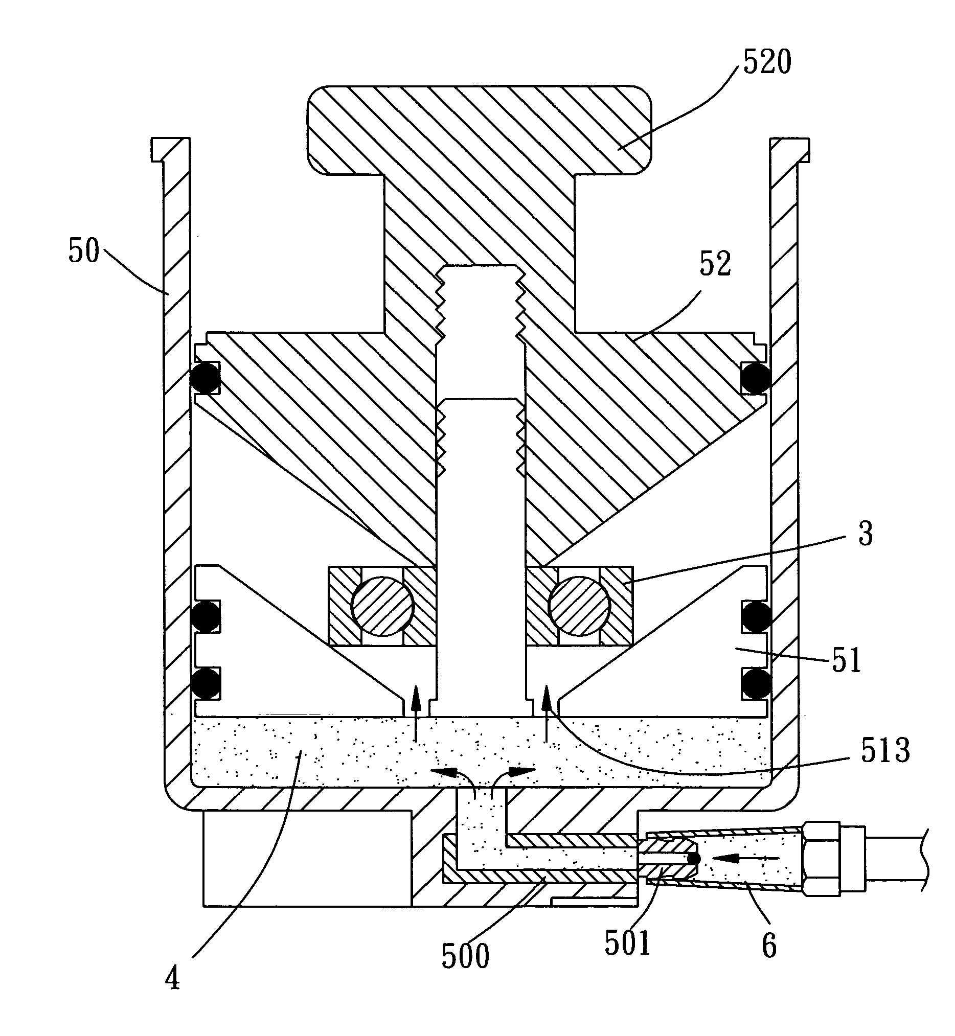
[0031] With reference to the drawings and in particular to FIGS. 4-6, a pneumatic grease applicator constructed in accordance with the present invention, generally designated with reference numeral 5, comprises a grease receptacle 50, a bearing retainer 51, a presser 52, and dustproof cover 53. The receptacle 50 comprises a container having a top opening and a closed bottom. The bottom of the receptacle 50 defines an opening or channel 500 to which a nozzle 501 is mounted. The nozzle 501 is releasably engageable with a pneumatic grease gun 6, which supplies grease (which is indicated by reference numeral 4, and hatched, in FIGS. 8 and 9), under a pneumatically induced driving force, through the nozzle 501 into the receptacle 50.

[0032] The bearing retainer 51 is movably received in the receptacle 50 and has a bottom face opposing the closed bottom of the receptacle 50 to define therebetween a closed space into which grease from the grease gun 6 is fed. The retainer 51 also has an op...


PUM


Abstract

Disclosed is a pneumatic grease applicator includes a receptacle in which a retainer that retains a bearing to which grease is to be applied and a presser that securely holds the presser on the retainer are movably received. The receptacle has a bottom nozzle through which grease is continuously supplied from an external source under a pneumatically induced driving force, whereby the grease can be consecutively applied to a number of bearings without interrupts. Sealing members are provided between the retainer and the presser and side wall of the receptacle to prevent leakage of grease.

Description

BACKGROUND OF THE INVENTION [0001] 1. Field of the Invention [0002] The present invention relates generally to a grease applicator that is employed to apply grease to mechanical elements, such as a bearing, and in particular to a pneumatically operated grease applicator in which grease is supplied and driven to cover over the bearing by pneumatic force. [0003] 2. The Related Art [0004] Bearings are commonly employed in heavy machinery to support relative displacement and rotation between mechanical elements. Lubrication is one of the most important factors for maintaining operation and service life of the bearing. Lubrication of the bearing is commonly done by manually applying grease into and over the bearing. Workers apply the grease to the bearing by bear hands or hands with gloves. This often causes contamination of articles surrounding the working site or the dresses of the workers by being unexpected or accidentally contacted by the workers' hands. [0005] A grease applicator, ...

Claims


Application Information

Patent Timeline
IPC IPC(8): F16C1/24
CPCF16N37/003F16C33/6625F16C19/06F16C43/04
Inventor LIAO, PO-LIN
Owner LIH YANN INDAL
Why Eureka
Try Eureka