Non-volatile programmable logic gates and adders

a programmable logic gate and non-volatile technology, applied in logic circuits using specific components, pulse techniques, instruments, etc., can solve problems such as the inability to realize complex logic functions with magnetic logic devices employing magnetic fields, and the inability to propose designs

Active Publication Date: 2011-03-24
EVERSPIN TECHNOLOGIES
View PDF99 Cites 8 Cited by
  • Summary
  • Abstract
  • Description
  • Claims
  • Application Information

AI Technical Summary

Problems solved by technology

However, there are deficiencies in the proposed designs.
Until this disclosure, complex logic functions can not be realized with magnetic logic devices employing magnetic fields.

Method used


Image

  • Non-volatile programmable logic gates and adders
  • Non-volatile programmable logic gates and adders
  • Non-volatile programmable logic gates and adders

Examples


Embodiment Construction

[0023]In the following description, reference is made to the accompanying set of drawings that form a part hereof and in which are shown by way of illustration several specific embodiments. It is to be understood that other embodiments are contemplated and may be made without departing from the scope or spirit of the present invention. The following detailed description, therefore, is not to be taken in a limiting sense. While the present invention is not so limited, an appreciation of various aspects of the invention will be gained through a discussion of the examples provided below.

[0024]All scientific and technical terms used herein have meanings commonly used in the art unless otherwise specified. The definitions provided herein are to facilitate understanding of certain terms used frequently herein and are not meant to limit the scope of the present disclosure.

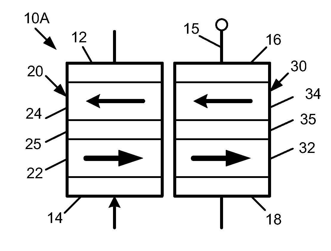
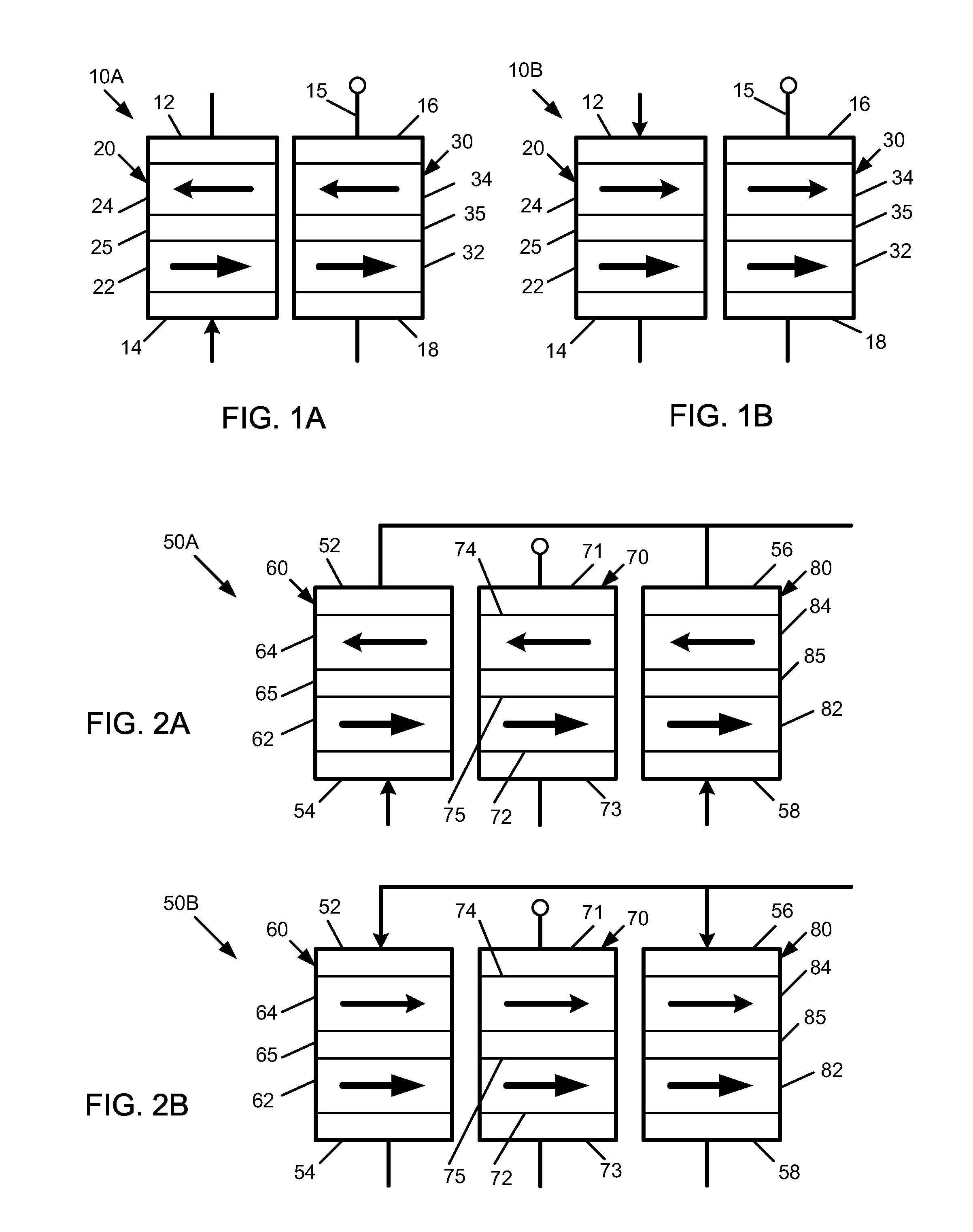
[0025]Referring to FIGS. 1A and 1B, an embodiment of a magnetic logic device 10A, 10B, respectively, is diagrammaticall...


PUM


Abstract

Spin torque magnetic logic device having at least one input element and an output element. Current is applied through the input element(s), and the resulting resistance or voltage across the output element is measured. The input element(s) include a free layer and the output element includes a free layer that is electrically connected to the free layer of the input element. The free layers of the input element and the output element may be electrically connected via magnetostatic coupling, or may be physically coupled. In some embodiments, the output element may have more than one free layer.

Description

PRIORITY[0001]This application is a continuation of U.S. patent application Ser. No. 12 / 125,975 entitled, “NON-VOLATILE PROGRAMMABLE LOGIC GATES AND ADDERS”, filed on May 23, 2008, the disclosure of which is incorporated herein by reference thereto.BACKGROUND[0002]This application relates to spin torque transfer devices.[0003]Spin torque transfer technology, also referred to as spin electronics, combines semiconductor technology and magnetics, and is a more recent development. In spin electronics, the spin of an electron, rather than the charge, is used to indicate the presence of digital information. The digital information or data, represented as a “0” or “1”, is storable in the alignment of magnetic moments within a magnetic element. The resistance of the magnetic element depends on the moment's alignment or orientation. The stored state is read from the element by detecting the component's resistive state.[0004]The magnetic element, in general, includes a ferromagnetic pinned la...

Claims


Application Information

Patent Timeline
Patent Type & Authority Applications(United States)
IPC IPC(8): H03K19/168H01L29/82
CPCH03K19/173G11C11/16G11C11/161G11C11/1673
Inventor XI, HAIWENLI, YANGXUE, SONG
Owner EVERSPIN TECHNOLOGIES
Why Eureka
Try Eureka