Display apparatus
- Summary
- Abstract
- Description
- Claims
- Application Information
AI Technical Summary
Benefits of technology
Problems solved by technology
Method used
Image


Examples
embodiment 1 (
1. Embodiment 1 (In the Case of an Externally Provided Liquid Crystal Lens)
[0099](A) General Configuration of the Liquid Crystal Display Apparatus
[0100]FIG. 1 is a view schematically showing a configuration of essential part of a liquid crystal display apparatus 100 in an embodiment 1.
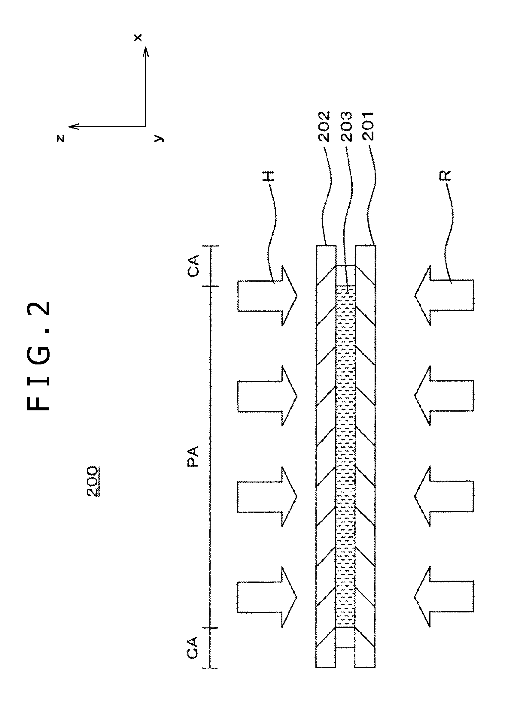
[0101]As shown in FIG. 1, the liquid crystal display apparatus 100 of the present embodiment includes a liquid crystal panel 200, a light amount adjustment section 210, a backlight 300 and a data processing device 400. The components are successively described.
[0102](A1) Outline of the Liquid Crystal Panel 200
[0103]The liquid crystal panel 200 is described.
[0104]As shown in FIG. 1, the liquid crystal panel 200 has a first polarizing plate 206 disposed on one face thereof in such a manner as to oppose to the liquid crystal panel 200 and has a second polarizing plate 207 disposed on the other face thereof in such a manner as to oppose to the liquid crystal panel 200. And, on the side of the one face, the...
embodiment 2 (
2. Embodiment 2 (In the Case of an Externally Provided Liquid Crystal Lens)
[0234]In the following, an embodiment 2 is described.
[0235](A) Configuration and so Forth of the Liquid Crystal Display Apparatus
[0236]FIG. 12 is a sectional view showing, in an enlarged scale, essential part of the liquid crystal display apparatus 100b in embodiment 2. In FIG. 12, a portion corresponding to pixels P provided in a pixel region PA is shown.
[0237]As shown in FIG. 12, the present embodiment is different from embodiment 1 in a second transparent electrode 62e_2 of a light amount adjustment section 210b. Except this, the present embodiment is similar to embodiment 1. Therefore, description of overlapping portions is omitted.
[0238]As shown in FIG. 12, the second transparent electrode 62e_2 of the light amount adjustment section 210b is formed in such a manner as to cover a face of the second glass substrate 212 on the side opposing to the first glass substrate 211 similarly as in the case of the em...
embodiment 3 (
3. Embodiment 3 (In the Case of an Externally Provided Liquid Crystal Lens)
[0288]In the following, an embodiment 3 is described.
[0289](A) Configuration and so Forth of the Liquid Crystal Display Apparatus
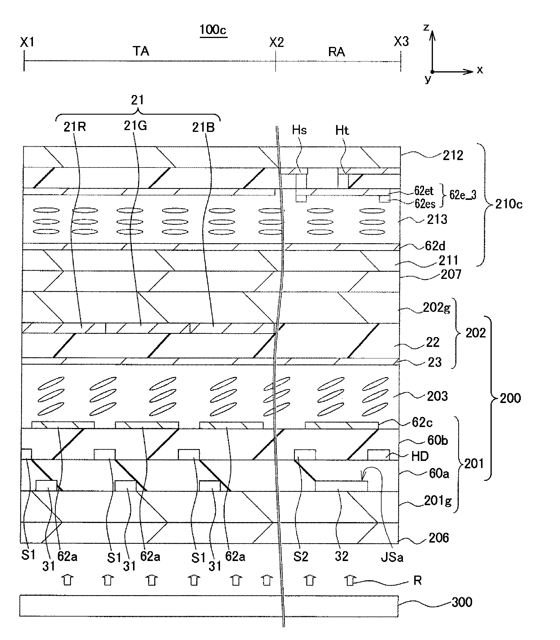
[0290]FIG. 19 is a sectional view showing essential part of the liquid crystal display apparatus 100c in the embodiment 3 in an enlarged scale. In FIG. 19, a portion corresponding to pixels P provided in a pixel region PA is shown.
[0291]As shown in FIG. 19, the present embodiment is different from embodiment 1 in a second transparent electrode 62e_3 of a light amount adjustment section 210c. Except this, the present embodiment is similar to the embodiment 1. Therefore, description of overlapping portions is omitted.
[0292]As shown in FIG. 19, the second transparent electrode 62e_3 of the light amount adjustment section 210c is formed in such a manner as to cover a face of the second glass substrate 212 on the side opposing to the first glass substrate 211 similarly as in the case of ...
PUM
 Abstract
Description
Claims
Application Information
 - R&D
- Intellectual Property
- Life Sciences
- Materials
- Tech Scout
- Unparalleled Data Quality
- Higher Quality Content
- 60% Fewer Hallucinations
Browse by: Latest US Patents, China's latest patents, Technical Efficacy Thesaurus, Application Domain, Technology Topic, Popular Technical Reports.
© 2025 PatSnap. All rights reserved.Legal|Privacy policy|Modern Slavery Act Transparency Statement|Sitemap|About US| Contact US: help@patsnap.com