

Liquid crystal display
a liquid crystal display and contrast ratio technology, applied in optics, instruments, non-linear optics, etc., can solve the problem of low contrast ratio, and achieve the effect of improving the contrast ratio of liquid crystal displays
- Summary
- Abstract
- Description
- Claims
- Application Information
AI Technical Summary
Benefits of technology
Problems solved by technology
Method used
Image

Examples
example 1
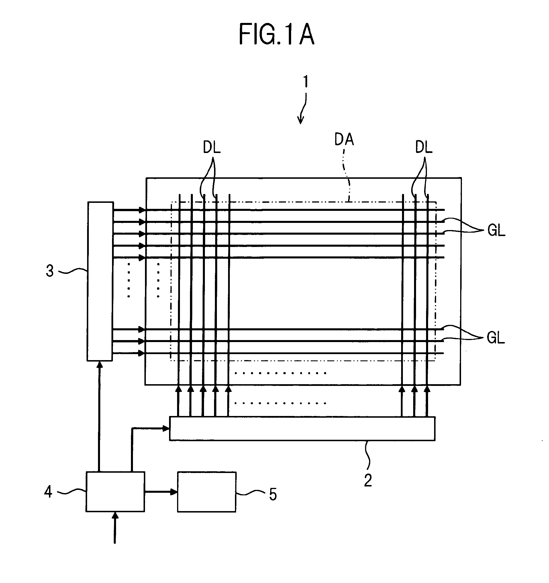
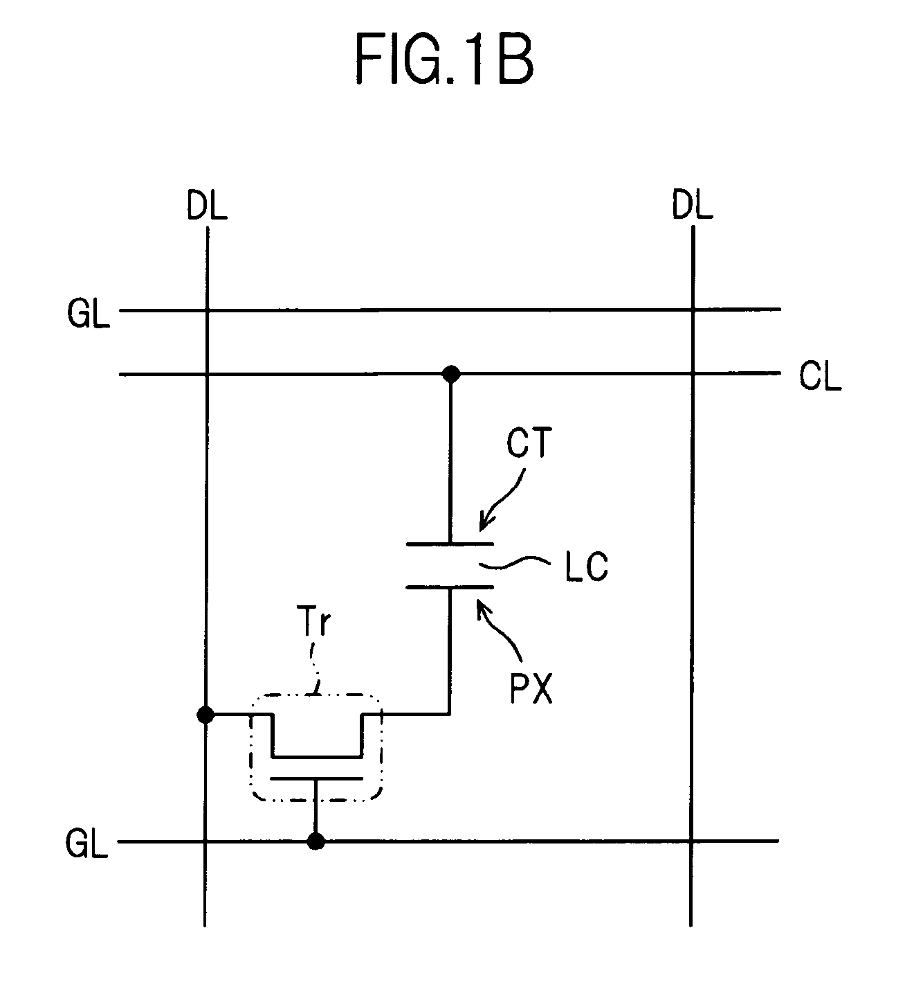
[0109]FIGS. 4A to 4F are schematic diagrams showing an example of a simplified configuration of an IPS-mode liquid crystal display panel according to Example 1 of the present invention.
[0110]FIG. 4A is a schematic plan view showing an example of a plan-view structure of one pixel of an active matrix substrate in a liquid crystal display panel of Example 1. FIG. 4B is a schematic plan view showing an example of a plan-view structure when an opposed substrate is overlaid on the region shown in FIG. 4A. FIG. 4C is a schematic sectional view showing an example of a sectional structure along the line B-B in FIGS. 4A and 4B. FIG. 4D is a schematic sectional view showing an example of a sectional structure along the line C-C in FIGS. 4A and 4B. FIG. 4E is a schematic sectional view showing an example of a sectional structure along the line D-D in FIGS. 4A and 4B. FIG. 4F is a schematic sectional view showing an example of a sectional structure along the line E-E in FIGS. 4A and 4B.
[0111]Th...
example 2
[0145]FIGS. 5A to 5C are schematic diagrams showing an example of a simplified configuration of an FFS-mode liquid crystal display panel according to Example 2 of the present invention.
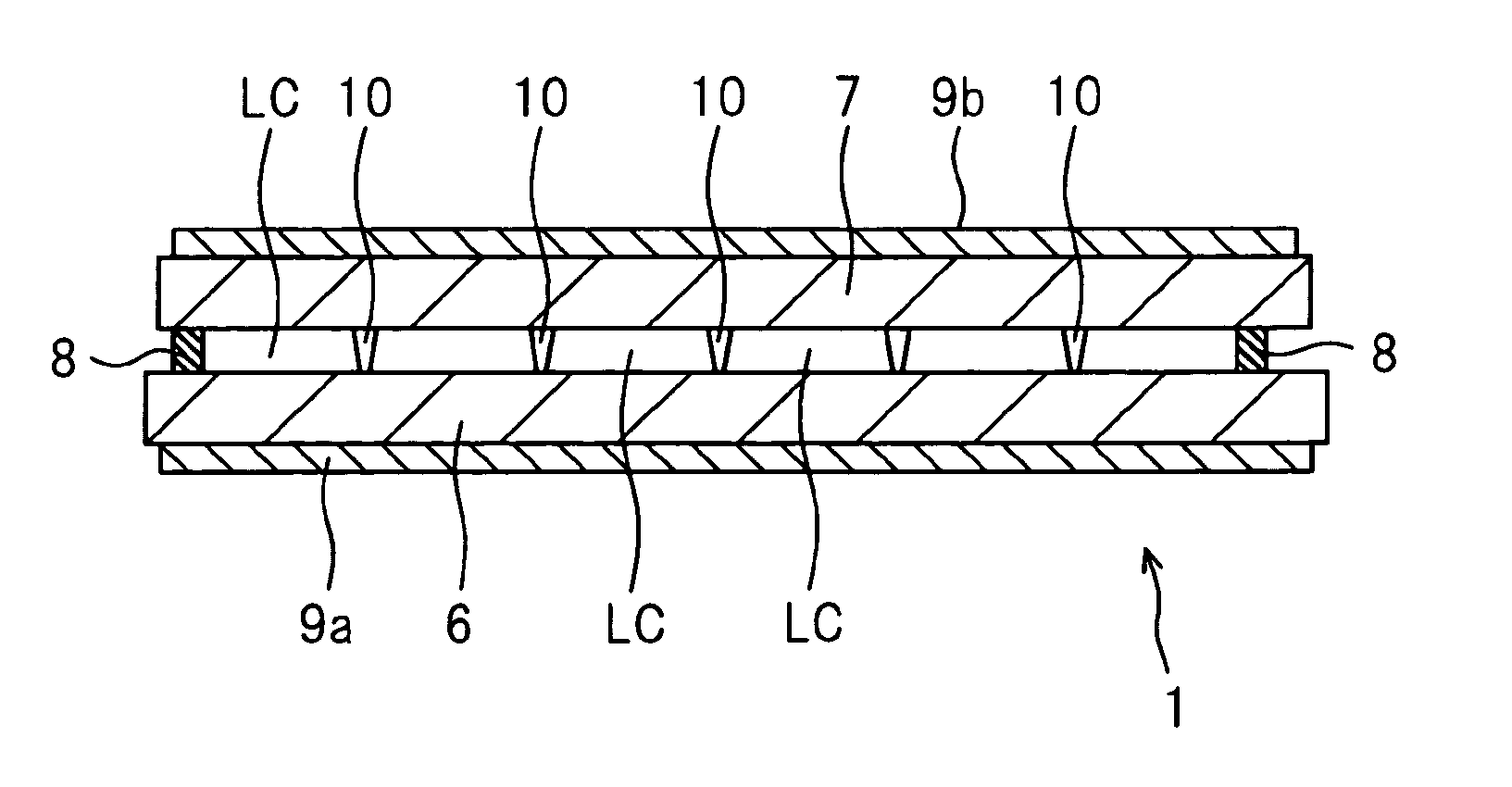
[0146]FIG. 5A is a schematic plan view showing an example of a plan-view structure of one pixel of an active matrix substrate 6 in a liquid crystal display panel of Example 2. FIG. 5B is a schematic sectional view showing an example of a sectional structure along the line F-F in FIG. 5A. FIG. 5C is a schematic sectional view showing an example of a sectional structure along the line G-G in FIG. 5A.
[0147]FIGS. 5B and 5C also show the liquid crystal layer LC (liquid crystal materials) and the opposed substrate 7 which are present on the active matrix substrate 6.
[0148]In Example 2, an IPS-mode liquid crystal display panel will be described as an example of the liquid crystal display panel 1 according to the present invention. Moreover, in Example 2, the case where one pixel of the liquid crystal display...
example 3
[0170]In this example, liquid crystal display panel 1 of Example 2 was manufactured using a liquid crystal mixture obtained by mixing liquid crystal materials JC1041XX and liquid crystal materials 5CB and T15 (available from Merck Corporation) with a mixture ratio of 50 / 40 / 10 (mol %) as the liquid crystals of the liquid crystal layer LC. And, the liquid crystal displays of this example, three kinds of liquid crystal materials in which the binaphthyl derivative was added to different concentrations similarly to Example 1 were used. In this example, the liquid crystal displays were manufactured similarly to Example 2 except for the above-mentioned matters.
[0171]The present inventors measured the transmittance under the crossed Nicol state similarly to Example 2 using a unit cell made from glass made up of the above-mentioned liquid crystal materials and found that the unit cell showed an extremely low transmittance as low as 0.05% or lower. Moreover, the stability at room temperature ...
PUM
| Property | Measurement | Unit |
|---|---|---|
| Transparency | aaaaa | aaaaa |
| Nanoscale particle size | aaaaa | aaaaa |
| Nanoscale particle size | aaaaa | aaaaa |
Abstract
Description
Claims
Application Information