Accelerated Weathering Test Apparatus with Calibration-Access Assembly

a test apparatus and weathering technology, applied in the field of accelerated weathering test apparatuses having a calibration-access assembly, can solve the problems of expensive accidents, test and calibration modules must be removed from the door pockets, and suffer a number of drawbacks

Active Publication Date: 2011-04-07
ATLAS MATERIAL TESTING TECH L L C
View PDF29 Cites 15 Cited by
  • Summary
  • Abstract
  • Description
  • Claims
  • Application Information

AI Technical Summary

Problems solved by technology

However, these conventional configurations suffer a number of drawbacks relating to sensor accuracy, operator safety, and accessibility.
A major disadvantage of this configuration is that the test and calibration modules fall out of the pockets when the door is opened resulting in an expensive accident.
Another disadvantage is that the test and calibration modules must be removed from the door pockets before the door is opened.
This is a serious hindrance and inconvenience to operation of the device.
While the above-discussed references offer unique configurations for accessing a sealed chamber, several drawbacks still exist.
While this configuration is desirable for applications involving pathogenic organisms, it is ill-suited for applications involving sensitive electronic equipment.
Specifically, removing sensitive electronic equipment, such as sensors, through a liquid-filled well would likely cause serious damage to the electronics, rendering them inoperable for their intended purpose.
A drawback associated with Hugh et al. is that the sensors are not mounted within the test chamber itself, but rather in the base of the moveable drawer.
While this configuration makes the sensors accessible when the drawer is pulled out, it leads to serious sensor-alignment issues.
Specifically, because the sensors are mounted on a moveable plane (the bottom of the drawer), it is difficult to ensure that the sensors obtain readings from the same disposition each time a reading is taken.
This type of configuration negatively affects the sensors ability to return accurate readings.
One such drawback is the possibility for operator injury.
In so doing, the operator could be exposed to harmful ultra-violet radiation emanating from the apparatus light sources.
Applying either of these methods to open the Q-Lab device's apparatus door would violate European Union safety regulations.
Additionally, other disadvantages of such a configuration include sensor alignment issues due to tolerance stackup, corrosion of connectors due to moisture breach, and difficult for operators to access the sensors.

Method used


Image

  • Accelerated Weathering Test Apparatus with Calibration-Access Assembly
  • Accelerated Weathering Test Apparatus with Calibration-Access Assembly
  • Accelerated Weathering Test Apparatus with Calibration-Access Assembly

Examples


Embodiment Construction

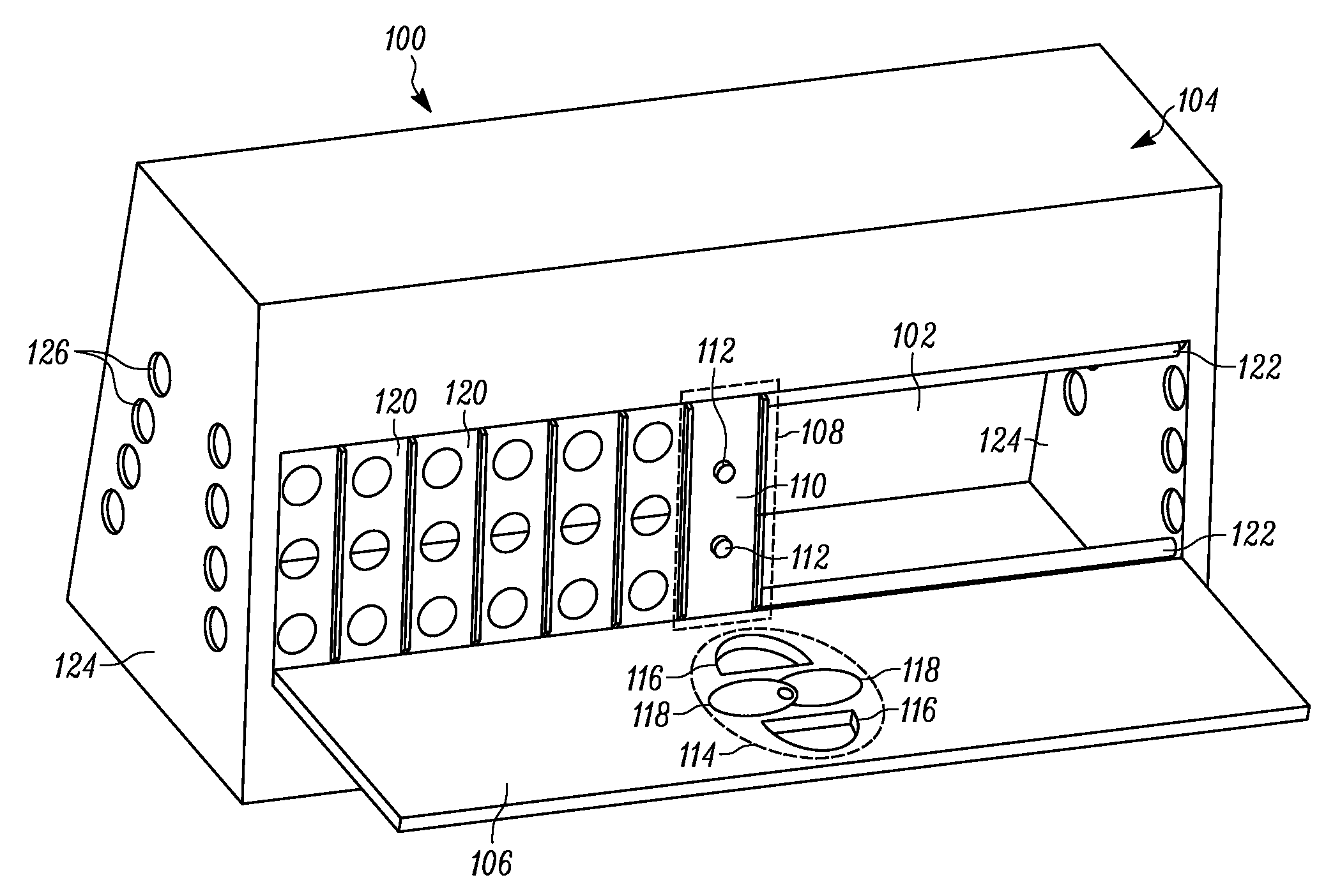
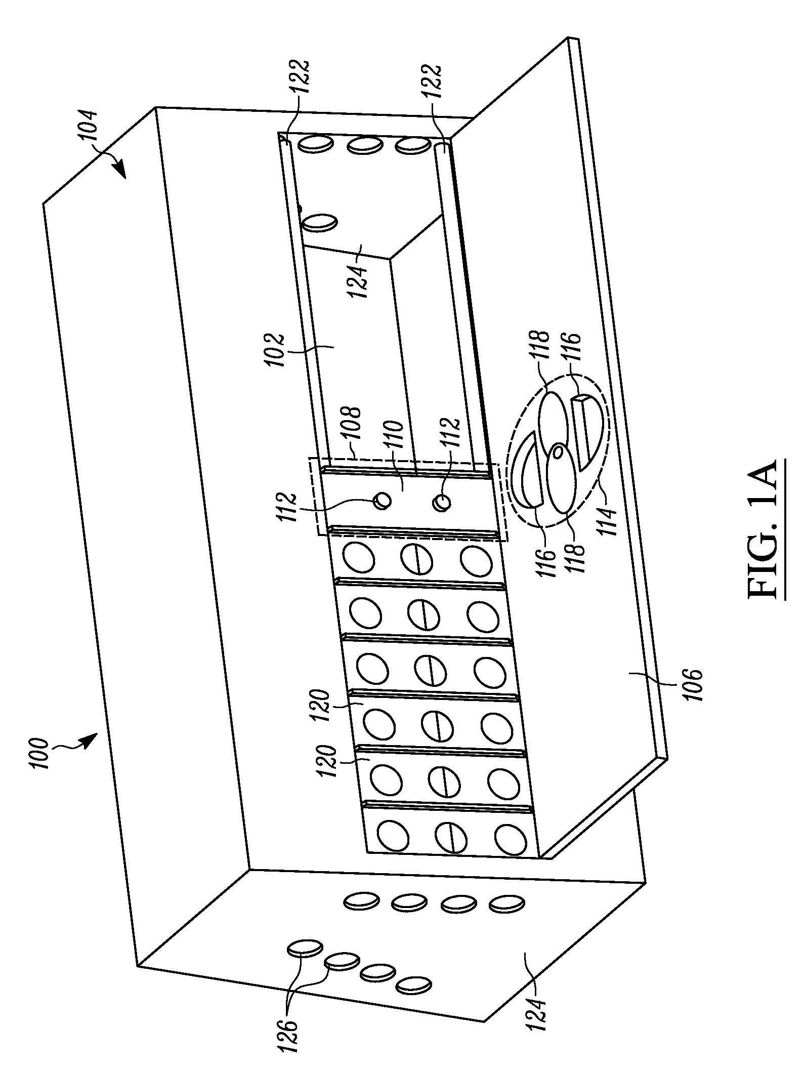
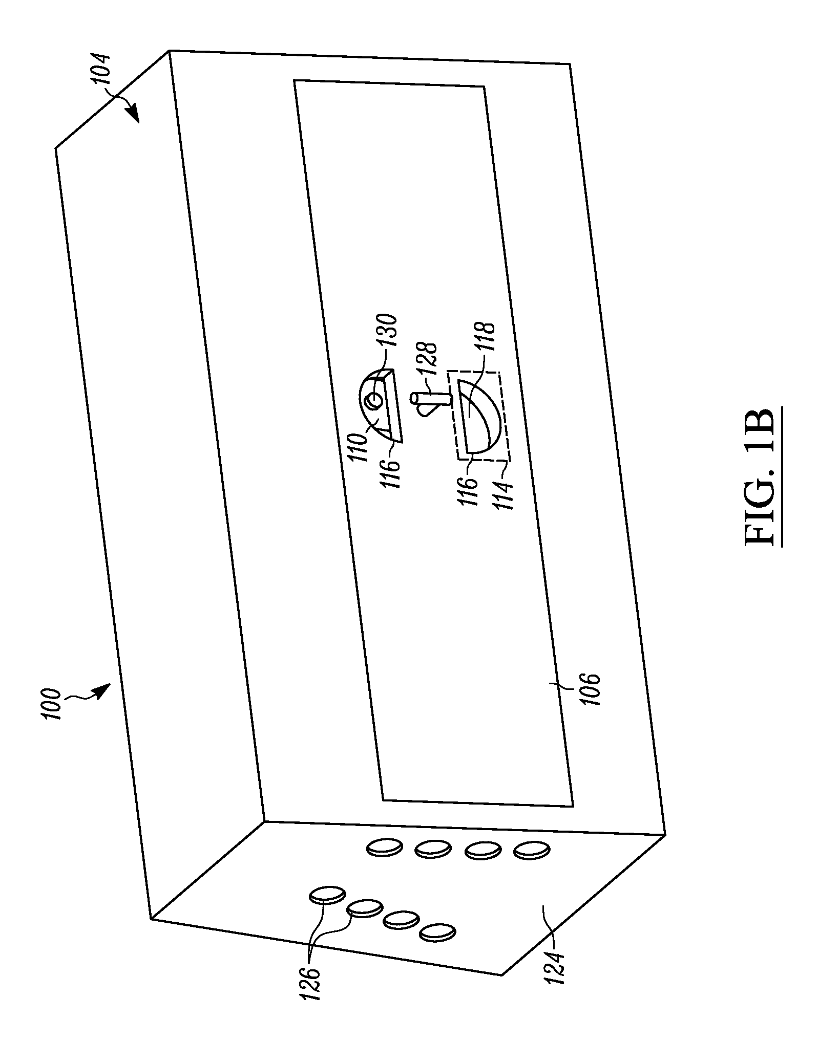
[0024]FIG. 1A shows a detailed perspective view of an enclosure portion 104 of an accelerated weathering apparatus 100 in accordance with the present invention. The apparatus 100 includes an enclosure 104 having at least one door 106 for access to a test chamber 102 defined within the enclosure 104. Only one door 106 will be discussed herein. However, it will be recognized by those of skill in the art that another door disposed in opposition may be identical in form and function. The test chamber 102 is generally defined within the enclosure 104. The enclosure 104 further includes an internal frame and enclosure sidewalls 124. A first door 106 is pivotally mounted to opposing enclosure sidewalls 124 and is in opposition to the second door (not shown), which is pivotally mounted to enclosure sidewalls 124. The door 106 provides access to the test chamber 102. A specimen mounting apparatus 232 (best shown in FIG. 2) is disposed within the test chamber 102 for supporting specimen holde...


PUM

PropertyMeasurementUnit
electrically conductiveaaaaaaaaaa
perimeteraaaaaaaaaa
irradianceaaaaaaaaaa

Abstract

An apparatus for accelerating the weathering effects on test specimens within a test chamber including a calibration-access assembly for replacing test sensors located within the apparatus with reference sensors when the apparatus door is closed. An improved sensor support assembly is also included. The calibration-access assembly from an improved location, facilitating superior irradiance detection. The calibration-access assembly including an aperture defined in the door of the apparatus and a shield connected to the door that is movable to permit or prevent access to sensors when the apparatus door is closed.

Description

FIELD OF THE INVENTION[0001]The present invention relates to an apparatus for accelerating the weathering effects on test specimens, and more particularly, to an accelerated weathering apparatus having a calibration-access assembly for safely and conveniently accessing sensors for calibration.BACKGROUND OF THE INVENTION[0002]A conventional testing apparatus will frequently contain a sealed chamber that creates a controlled environment wherein testing may occur. It is often necessary to locate sensors within such a chamber to detect the conditions within the controlled environment. These sensors must be periodically calibrated for accuracy. Conventional apparatuses utilize several different configurations in an effort to provide access to the sensors for calibration. However, these conventional configurations suffer a number of drawbacks relating to sensor accuracy, operator safety, and accessibility.[0003]Various attempts have been made to improve on the drawbacks associated with co...

Claims


Application Information

Patent Timeline
Patent Type & Authority Applications(United States)
IPC IPC(8): G01D18/00G01N17/00
CPCB01L1/00G01N2035/00306G01N17/004
Inventor SCHULTZ, RICHARDDONATO, RICHARD D.
Owner ATLAS MATERIAL TESTING TECH L L C
Why Eureka
Try Eureka