Automated Bathroom-stall Door

a technology for bathroom stalls and doors, applied in the direction of instruments, process and machine control, testing/monitoring control systems, etc., can solve the problems of lack of physical space requirements for apparatuses, inability to adapt apparatuses for stalls, and failure to successfully operate and lock hands-free a bathroom stall door

Active Publication Date: 2011-04-07
IBSIES FADI
View PDF9 Cites 41 Cited by
  • Summary
  • Abstract
  • Description
  • Claims
  • Application Information

AI Technical Summary

Benefits of technology

[0006]In a first preferred embodiment, the present invention comprises an improved apparatus for automatically opening, closing, locking, and unlocking a swinging bathroom stall door. This improved apparatus includes a first proximity sensor array comprising three linearly disposed sensors, each sensor further including a light-emitting-diode display device consisting of at least two colors, for example red and green, the first proximity sensor array arranging on a first side of the swinging door, that is outside-the-stall side of the door. And, a second proximity sensor array comprising three linearly disposed sensors, each sensor further including a light-emitting-diode display device consisting of at least two colors, the first proximity sensor array arranging on a second side of the swinging door, that is inside the stall. Further, a first actuator in electrical communication with the first and second proximity sensor arrays and coupled to a locking mechanism enables locking of the stall door when a patron moves the hand left to right and unlocking when the hand moves right to left. The display shows three green LEDs when the stall door is opened, unlocked, and the stall is unoccupied. A third sensor detects the presence of the patron inside the stall and prevents a second (waiting) patron from opening the door. When the stall is locked and occupied, three red LED lights illuminate.
[0007]Also, a second actuator in electrical communication with the first and second proximity sensor arrays and coupled to a door opening / closing mechanism. Accordingly, the same sensor array can be used to detect motion to lock, open, close, and unlock the door and a controller in electrical communication with the first and second proximity sensor arrays includes the requisite programming sequences to determine the desired affect of the motion of the patron's hand and can further determine if the motion is left to right or right-to-left. The controller, accordingly, includes memory, a power source (either hard-wired into the grid, or an on-board, self-contained source such as replaceable and / or rechargeable batteries or any combination), and soft and hard programming including a control logic sequence programming that enables a first sequence of signals received from at least one of the proximity sensor arrays to open the swinging door, a second sequence of signals to close the swinging door, a third sequence of signals to lock the door and a fourth sequence of signals to unlock the door. Finally, as discussed, the corresponding associated light-emitting-diode display device displays at least one color corresponding to the sequence of signals received by the controller.

Problems solved by technology

From simple foot operated garbage can lids to removal of entry doors, varied attempts to render public bathrooms hygienic and eliminate hand-contact with fixtures has been limited to on-off, start-stop, or open-close operations of traditional facilities.
This apparatus is applied to an exit / entry door to a bathroom and is not adapted for use on a stall-door and a patron waves his or her hand within the detection zone of the proximity sensor, this movement activates the door to open.
Snell, however, does not contemplate adapting the apparatus for a stall-door, which typically is a much lighter door and lacks the physical space requirements for his apparatus.
Yet, to date, no attempts have been made to successfully operate and lock “hands-free” a bathroom stall door.
Further, there have been no successful attempts to enable hands-free opening and closing of the stall-door.
The stall door presents problems and challenges not contemplated by any prior-art attempts to automate bathroom facilities functions.

Method used


Image

  • Automated Bathroom-stall Door
  • Automated Bathroom-stall Door
  • Automated Bathroom-stall Door

Examples


Embodiment Construction

[0019]Possible preferred embodiments will now be described with reference to the drawings and those skilled in the art will understand that alternative configurations and combinations of components may be substituted without subtracting from the invention. Also, in some figures certain components are omitted to more clearly illustrate the invention.

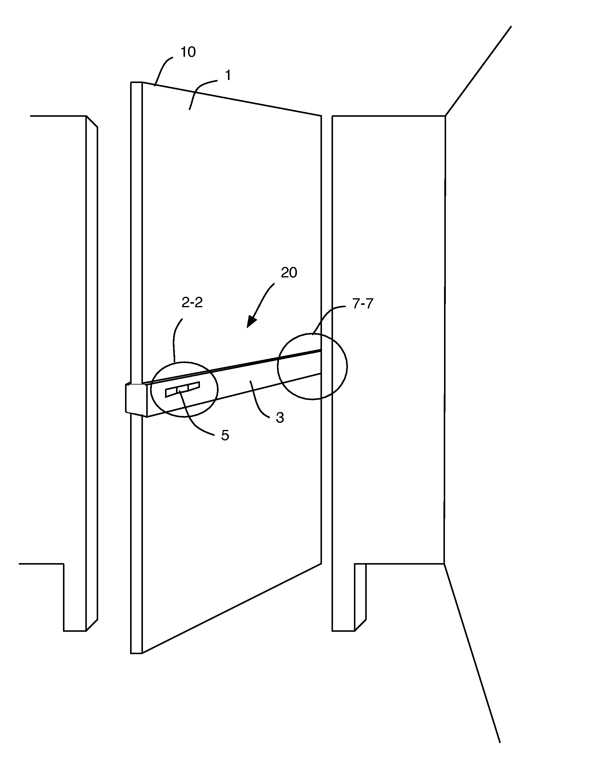
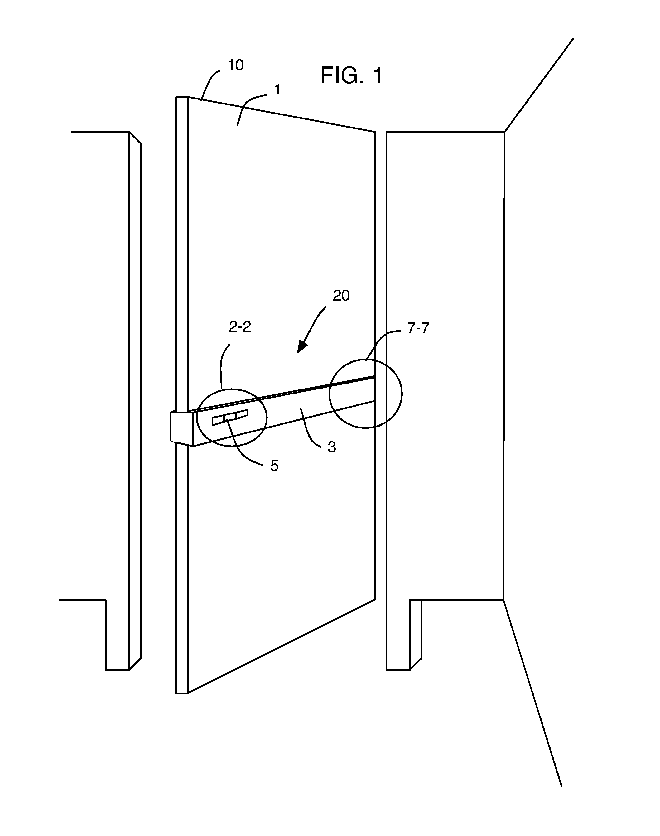
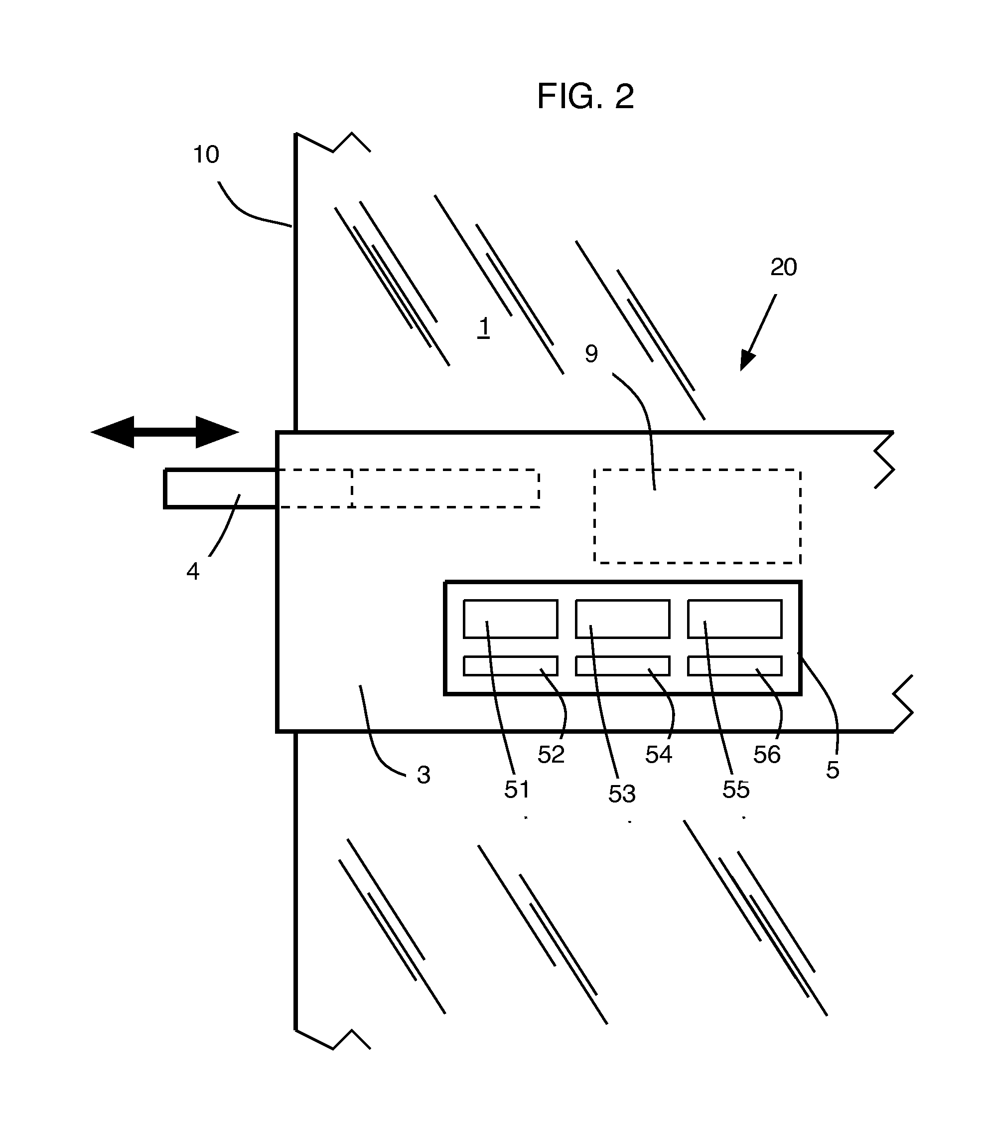
[0020]The present invention enables hands-free operation of a rest-room stall door from inside or outside and includes manual override from both sides. To prevent unintended opening of the stall-door the present invention includes sensors 14 to determine if the restroom stall is occupied. Accordingly, the improved apparatus 20 for automatically opening, closing, locking, and unlocking a swinging door includes a first actuator and power-assisted drive mechanism for opening and closing the door and a second actuator and associated power-assisted drive mechanism for locking and unlocking the door, a control unit, a power source (either on-bo...


PUM


Abstract

A first proximity sensor array arranged on a first side of a stall-door comprises three linearly aligned sensors whereby left-to-right movement of a patron's hand within the sensing zone causes a bathroom stall door to open. A second proximity sensor array arranged on a second side of the stall door comprises three linearly aligned sensors whereby right-to-left movement of a patron's hand within the sensing zone causes the door to close. A second right-to-left movement across the same second sensor array causes the stall door to lock and a first display array arranged on the first side of the door and a second display array arranged on the second side of the door alight, indicating the stall is occupied and locked. A left-to-right movement across the second sensor array causes the stall door to unlock and open, and the display arrays indicate the stall is available.

Description

FIELD OF THE INVENTION[0001]This invention relate to an apparatus and method of use for automatically opening, closing, locking, and unlocking a door and more specifically for hands-free operation of a bathroom stall-door.BACKGROUND[0002]Recently, many devices and systems have been introduced to automate and render “hands-free” various operating fixtures of public bathrooms. From simple foot operated garbage can lids to removal of entry doors, varied attempts to render public bathrooms hygienic and eliminate hand-contact with fixtures has been limited to on-off, start-stop, or open-close operations of traditional facilities.[0003]One attempt to provide a hands-free door-opening apparatus, described by Snell et al. in U.S. Pat. No. 7,068,179 on 27 Jun. 2006, includes an apparatus for automatically opening a swinging restroom door. It comprises an actuator, a control unit, and a power assisted drive mechanism and proximity sensor. This apparatus is applied to an exit / entry door to a b...

Claims


Application Information

Patent Timeline
Patent Type & Authority Applications(United States)
IPC IPC(8): G05B23/02
CPCE05B9/08E05F15/74E05B47/0002E05B47/0012E05B47/02E05B2047/002E05B2047/0026E05B2047/0056E05B2047/0086E05Y2400/822E05Y2400/86E05Y2900/112E05F15/00E05Y2400/852E05Y2600/46E05B41/00
Inventor IBSIES, FADI
Owner IBSIES FADI
Why Eureka
Try Eureka