
Image forming apparatus

Active Publication Date: 2011-04-07
HEWLETT PACKARD DEV CO LP
View PDF3 Cites 35 Cited by
  • Summary
  • Abstract
  • Description
  • Claims
  • Application Information

AI Technical Summary

Benefits of technology

[0010]Therefore, it is an aspect to provide an image forming apparatus which may achieve stable attachment / detachment of a developing device and stable transmission of drive power.
[0011]It is another aspect to provide an image forming apparatus which may prevent contamination of the surroundings due to developer leaked during attachment / detachment of a developing device.
[0017]A position of each of the plurality of driving coupling members is changed between an engaged position where the driving coupling member is engaged with the corresponding driven coupling member and a disengaged position where the driving coupling member is disengaged from the corresponding driven coupling member, and the gear and the cam member may be kept at a constant distance to prevent friction therebetween at the engaged position.
[0028]A position of each of the plurality of driving members may be changed between a transmission position where the driving member is engaged with the corresponding driven member to transmit power and a separated position where the driving member is disengaged from the corresponding driven member so as not to transmit power, and the gear and the cam member may be kept at a constant distance to prevent friction therebetween at the transmission position.
[0032]A position of each of the plurality of driving coupling members may be changed between an engaged position where the driving coupling member is engaged with the corresponding driven coupling member and a disengaged position where the driving coupling member is disengaged from the corresponding driven coupling member, and the gear and the cam member may be kept at a constant distance to prevent friction therebetween at the engaged position.

Problems solved by technology

However, the above described conventional image forming apparatus may have unstable coupling and power-transmission between the developing device and the drive device.
In addition, if the developing device is divided into a developing process device to perform an image forming process and a developer replenishment device to replenish developer in the developing process device, developer may leak during mounting of the developer replenishment device, causing contamination of the surroundings.

Method used


Image

  • Image forming apparatus
  • Image forming apparatus
  • Image forming apparatus

Examples


Embodiment Construction

[0048]Reference will now be made in detail to the embodiments, examples of which are illustrated in the accompanying drawings, wherein like reference numerals refer to like elements throughout.

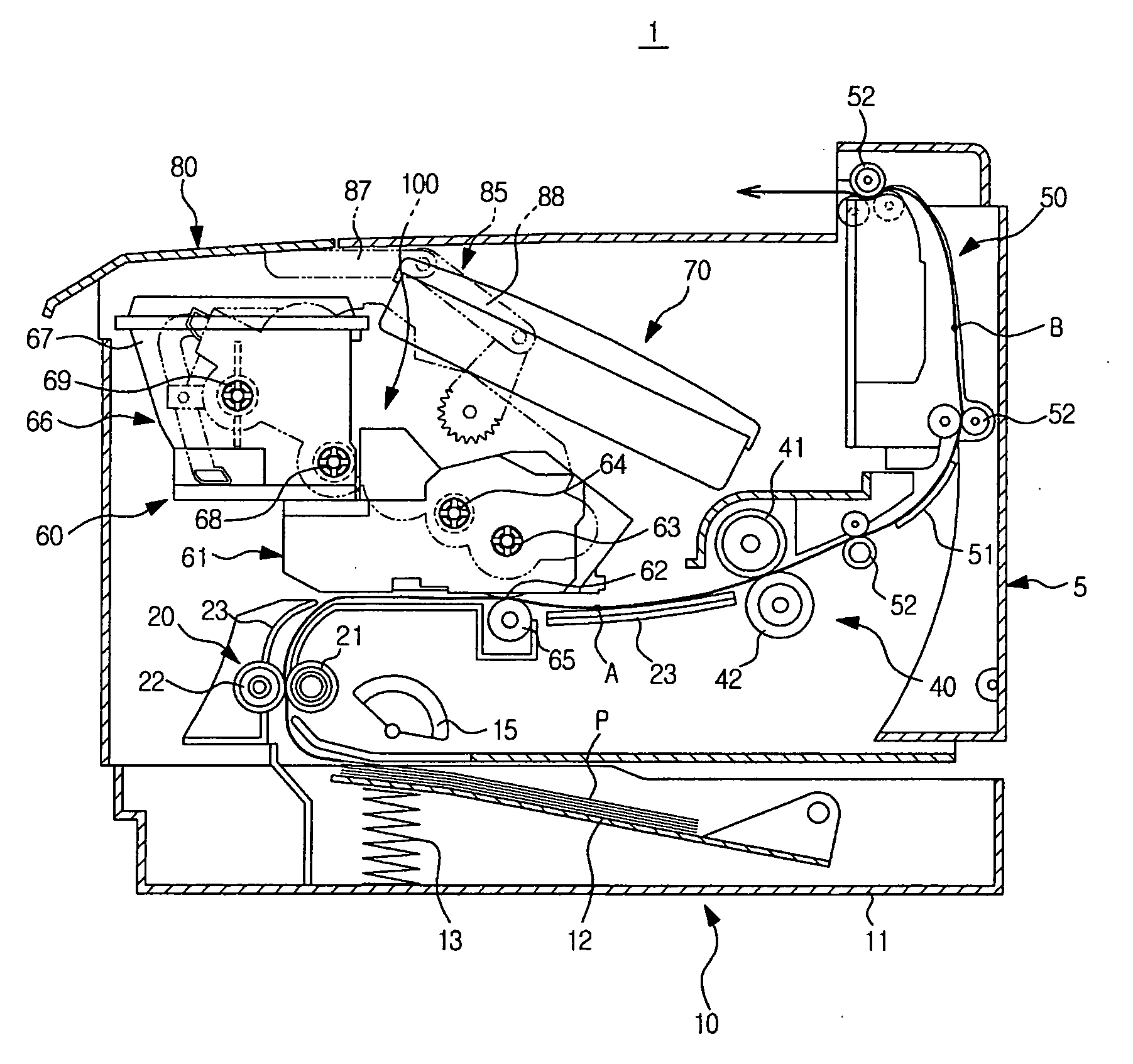
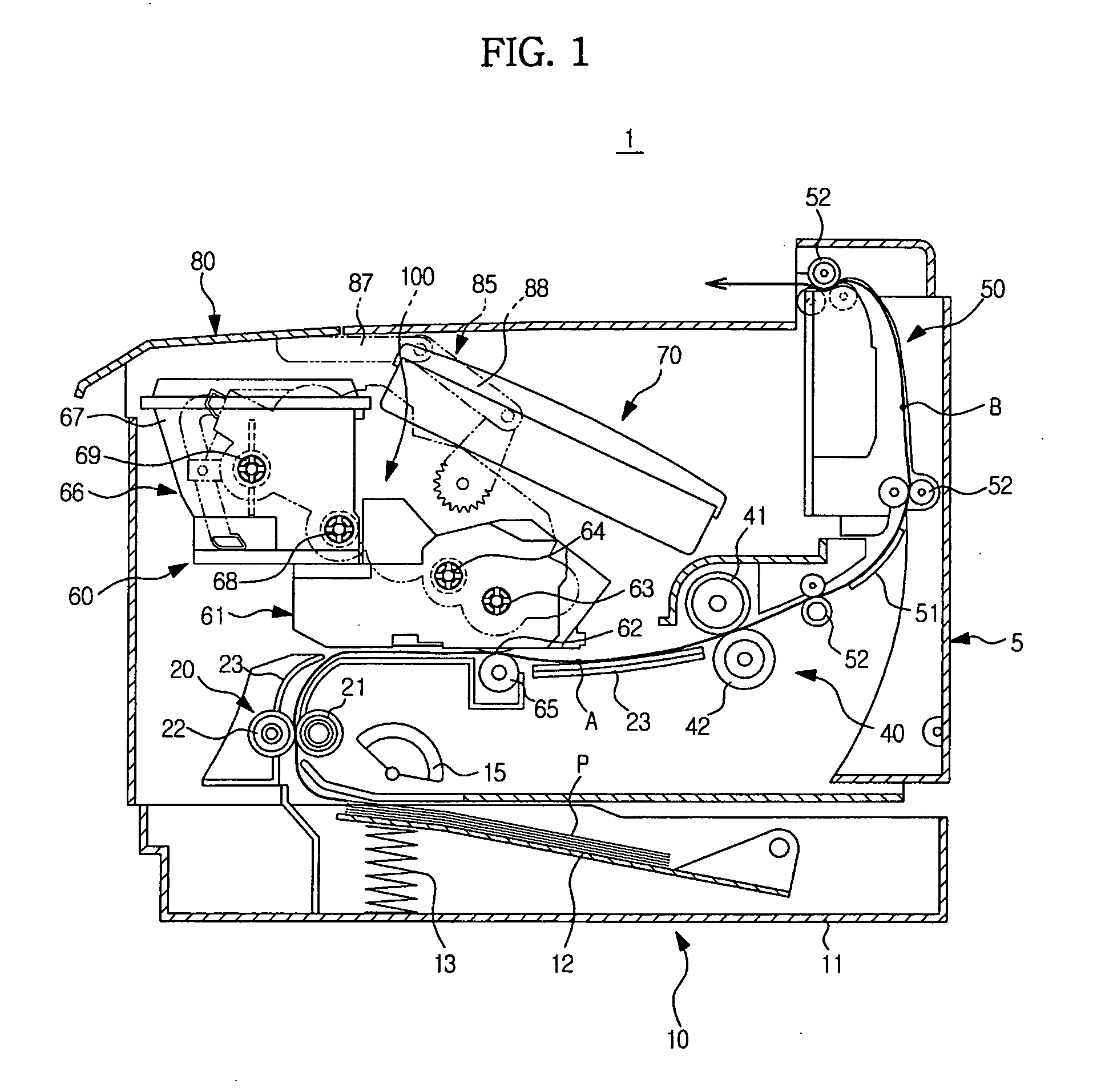
[0049]FIG. 1 is a view illustrating an interior configuration of an image forming apparatus according to an embodiment.

[0050]As illustrated in FIG. 1, the image forming apparatus 1 includes a body 5, a paper supply device 10 in which paper P is loaded, a feeding device 20 to feed the paper P, a developing device 60 to form an image on the paper P, a drive device 100 to drive the developing device 60, a fusing device 40 to fuse the image to the paper P, a discharge device 50 to discharge the paper P, and a cover 80 to be opened away from or closed to an upper front portion of the body 5.

[0051]The paper supply device 10 serves to supply the paper P and is installed below the body 5. The paper supply device 10 includes a paper supply tray 11 in the form of a cassette, and a press plate 12 and a p...


PUM


Abstract

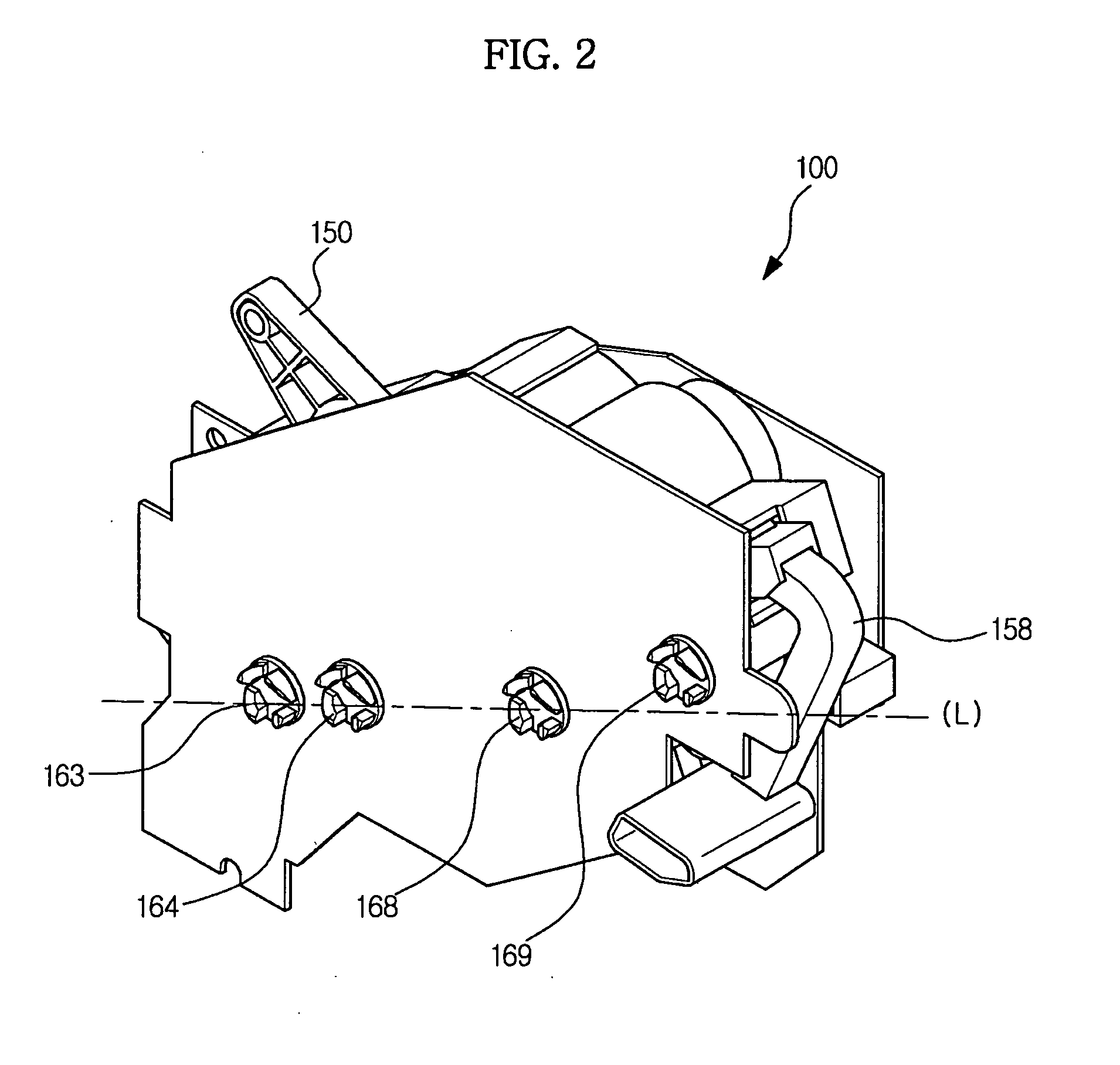
An image forming apparatus to achieve stable attachment / detachment of a developing device and stable power transmission while preventing contamination of the surroundings due to leakage of developer. The image forming apparatus includes a cover to be opened away from or closed to an upper surface of a body, and a drive device provided at a side of the developing device so as to be coupled with or released from the developing device and be moved in linkage with opening / closing of the cover. The developing device includes driven coupling members to be rotated upon receiving drive power from the drive device. The drive device includes driving coupling members engaged with the driven coupling members, and a moving member to horizontally move the driving coupling members according to the opening / closing of the cover and to control the engagement / disengagement of the driving coupling members and the driven coupling members.

Description

CROSS-REFERENCE TO RELATED APPLICATIONS[0001]This application claims the benefit of Korean Patent Application No. 2009-0094689, filed on Oct. 6, 2009 in the Korean Intellectual Property Office, the disclosure of which is incorporated herein by reference.BACKGROUND[0002]1. Field[0003]Embodiments relate to an image forming apparatus to enable stable operation.[0004]2. Description of the Related Art[0005]Generally, image forming apparatuses are devised to form an image on a printing medium according to input signals. Examples of image forming apparatuses include printers, copiers, fax machines, and devices combining functions thereof.[0006]In an image forming apparatus, after light is irradiated to a photoconductor that has been charged with a predetermined electric potential to form an electrostatic latent image on a surface of the photoconductor, toner, i.e. developer is fed to the electrostatic latent image, forming a visible image. The toner image, formed on the photoconductor, is ...

Claims


Application Information

Patent Timeline
IPC IPC(8): G03G15/00G03G15/04
CPCG03G21/1857G03G2221/169G03G21/1676G03G21/1647G03G21/1633
Inventor LEE, HAN JUN
Owner HEWLETT PACKARD DEV CO LP
Learn More