Dynamic real-time calibration for antenna matching in a radio frequency receiver system

Active Publication Date: 2011-04-14
RES IN MOTION LTD
View PDF58 Cites 52 Cited by
  • Summary
  • Abstract
  • Description
  • Claims
  • Application Information

AI Technical Summary

Problems solved by technology

The environment in which a wireless or radio frequency system is located often affects the operation of antennas associated with this system.
In mobile communication systems, poor operation may translate into undesired effects

Method used


Image

  • Dynamic real-time calibration for antenna matching in a radio frequency receiver system
  • Dynamic real-time calibration for antenna matching in a radio frequency receiver system
  • Dynamic real-time calibration for antenna matching in a radio frequency receiver system

Examples


Embodiment Construction

[0020]It should be understood at the outset that although an illustrative implementation of one or more embodiments are provided below, the description is not to be considered as limiting the scope of the embodiments described herein. The disclosure may be implemented using any number of techniques, whether currently known or in existence. The disclosure should in no way be limited to the illustrative implementations, drawings, and techniques illustrated and described herein, which may be modified within the scope of the appended claims along with a full scope of equivalence. It should be appreciated that for simplicity and clarity of illustration, where considered appropriate, the reference numerals may be repeated among the figures to indicate corresponding or analogous elements.

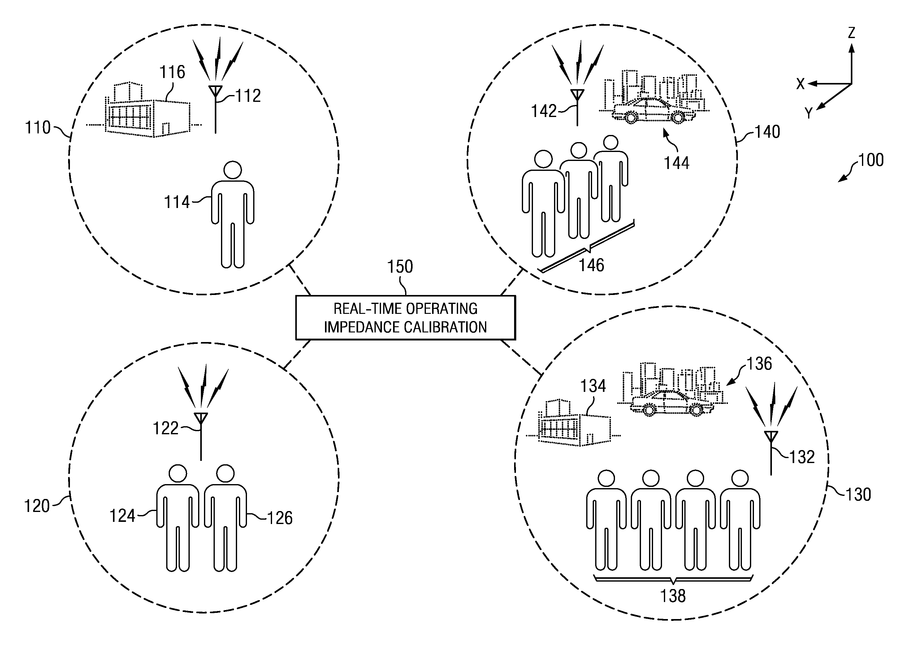
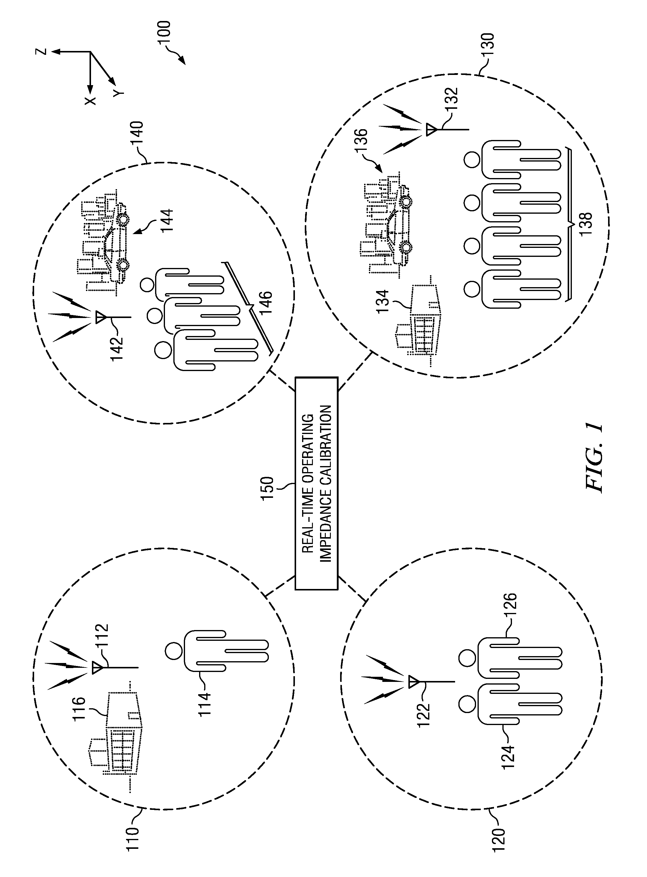
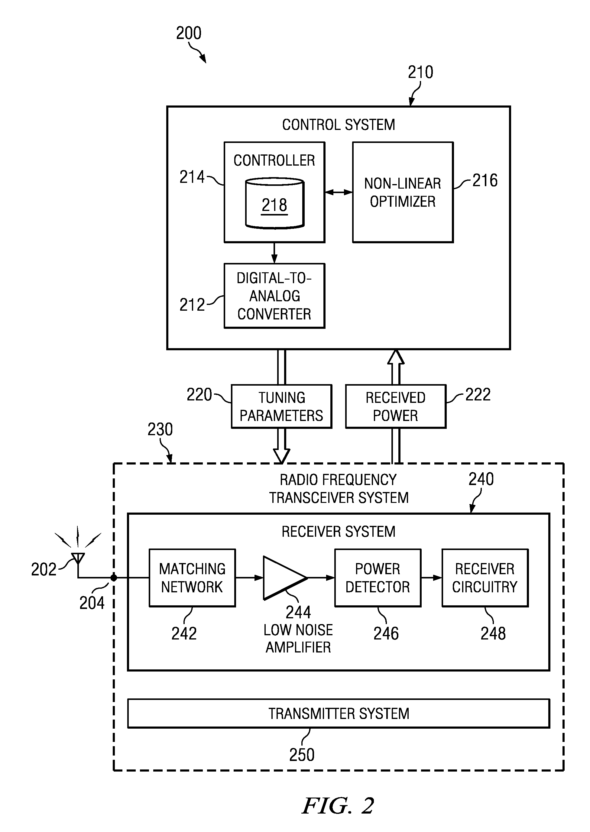
[0021]According to one illustrative embodiment, a wireless communication system comprises an antenna, a control system that calculates a value of an impedance of the antenna in real-time to match a load in...


PUM


Abstract

Real-time calibration of a tunable matching network that matches the dynamic impedance of an antenna in a radio frequency receiver system. The radio frequency receiver system includes two non-linear equations that may be solved to determine the reflection coefficient of the antenna. The tunable matching network is repeatedly perturbed and the power received by the antenna is measured after each perturbation at the same node in the matching network. The measured power values are used by an optimizer in converging to a solution that provides the reflection coefficient of the antenna. The reflection coefficient of the antenna may be used to determine the input impedance of the antenna. The elements of the matching circuit are then adjusted to match the input impedance of the antenna.

Description

CROSS-REFERENCE TO RELATED APPLICATIONS[0001]This application is related to U.S. patent application Ser. No. ______ (Attorney Docket No. 36251-US-PAT), entitled Dynamic Real-Time Calibration for Antenna Matching in a Radio Frequency Transmitter System, to Shirook Ali et al., filed on even date herewith, and which is herein incorporated by reference for all purposes.BACKGROUND[0002]1. Technical Field[0003]This disclosure relates to wireless communications and more specifically to the design and implementation of a wireless radio frequency receiver system that dynamically matches the impedance of an antenna in real-time.[0004]2. Description of the Related Art[0005]The environment in which a wireless or radio frequency system is located often affects the operation of antennas associated with this system. For example, the power delivered by an antenna changes with proximity to objects. These objects may include, for example, without limitation, a human object, a metal object, a car, an ...

Claims


Application Information

Patent Timeline
IPC IPC(8): H04B17/00H04B1/04H01Q1/50
CPCH01Q3/267H01Q1/50H03H7/40
Inventor ALI, SHIROOKWARDEN, JAMES PAULBAKR, MOHAMED
Owner RES IN MOTION LTD
Why Eureka
Try Eureka