

Power headroom reporting method and device for wireless communication system
a wireless communication system and power headroom technology, applied in the field of wireless communication systems, can solve the problems of reducing the transmission quality of uplinks, unable to measure channel path loss, and unable to meet the requirements of enb scheduling, etc., and achieve the effect of reducing the number of lte-outs
- Summary
- Abstract
- Description
- Claims
- Application Information
AI Technical Summary
Benefits of technology
Problems solved by technology
Method used
Image

Examples
first embodiment
[0044]In accordance with the present invention, a PHR is triggered when a path loss utilized in a last PHR has changed in value by more than a reference value, or when a predetermined time has elapsed after the transmission of the last PHR. Although the PHR may be triggered, a UE does not transmit the PHR immediately. but instead waits until a transmission is available. Specifically, the UE waits until an uplink transmission resource is allocated. After the PHR is triggered, the UE transmits the PHR on the first uplink transmission. The PHR is MAC layer control information, and is transmitted in an 8-bit PH MAC control element. The first two bits of the PH MAC control element are reserved, and the remaining 6 bits are used to indicate a PH level in a range between −23 dB and 40 dB.
[0045]As described above, when multiple carriers are aggregated, different PHRs are triggered for different carriers at different times. Thus, information is provided that specifies which uplink carrier is...
second embodiment
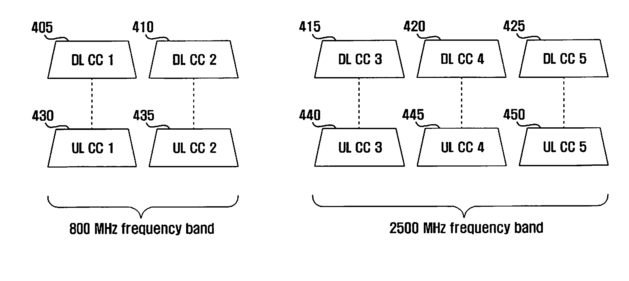
[0058]In the present invention, a relationship between an uplink carrier on which the PHR is transmitted (PHR-transmitting uplink carnal and an uplink carrier of which PH is calculated (PHR-designated uplink carrier) is predetermined. This relationship enables identification of the PHR-designated uplink carrier without changing a PHR format to insert a PHR ID. For example, a UE may aggregate 5 uplink carriers including two uplink carriers designated for PHR UL CC 1430 and UL CC 3 440, as shown in FIG. 4. The PHR for UL CC 1 430 can be transmitted on one of uplink carriers UL CC 1 430 and UL CC 2 435, and the PHR for UL CC 3 440 can be transmitted on one of uplink carriers UL CC 3 440, UL CC 4 445, and UL CC 5 450. This provides for quick PHR transmission without the use of additional PHR IDs.
[0059]Referring now to FIG. 7, a diagram illustrates operations of an LTE-A wireless communication system, according to the second embodiment of the present invention. In FIG. 7, a network 710 s...
third embodiment
[0068]Accordingly, in the present invention, when a new uplink carrier is configured / activated and configured for PHR, the UE acquires a valid path loss of a corresponding downlink carrier by measuring over a predetermined time and transmits the PHR at a first transmission chance after the measurement. For example, the UE does not generate / transmit a PHR even if a transmission chance is provided before a valid path loss measurement value has been obtained. The PHR is transmitted at the first transmission chance after a valid path loss measurement value is obtained. An uplink carrier is configured / activated when the ENB sends the UE configuration information about the uplink carrier and instructs the UE to prepare for transmission over the uplink carrier. The path loss of a downlink carrier is measured by measuring received strength of a reference signal on the downlink carrier and subtracting the measurement from the downlink transmission power.
[0069]FIG. 9 is a diagram illustrating...
PUM
 Abstract
Description
Claims
Application Information