Wall Anchor

Inactive Publication Date: 2011-04-28
HANRATTY BRENT
View PDF8 Cites 5 Cited by
  • Summary
  • Abstract
  • Description
  • Claims
  • Application Information

AI Technical Summary

Benefits of technology

[0007]The anchoring device comprises a shaft having a first end and a second end opposite the first end, and an anchor attached to the second end. The shaft may be hollow or provide other means for delivering a securing compound from one side of a wall to the opposite side of the wall. An entry port at the first end of the shaft receives a securing compound and delivers the securing compound to the second end of

Problems solved by technology

Others require complicated shapes or designs.
Some require multiple steps, while others

Method used


Image

  • Wall Anchor
  • Wall Anchor
  • Wall Anchor

Examples


Embodiment Construction

[0032]The detailed description set forth below in connection with the appended drawings is intended as a description of presently-preferred embodiments of the invention and is not intended to represent the only forms in which the present invention may be constructed or utilized. The description sets forth the functions and the sequence of steps for constructing and operating the invention in connection with the illustrated embodiments. However, it is to be understood that the same or equivalent functions and sequences may be accomplished by different embodiments that are also intended to be encompassed within the spirit and scope of the invention.

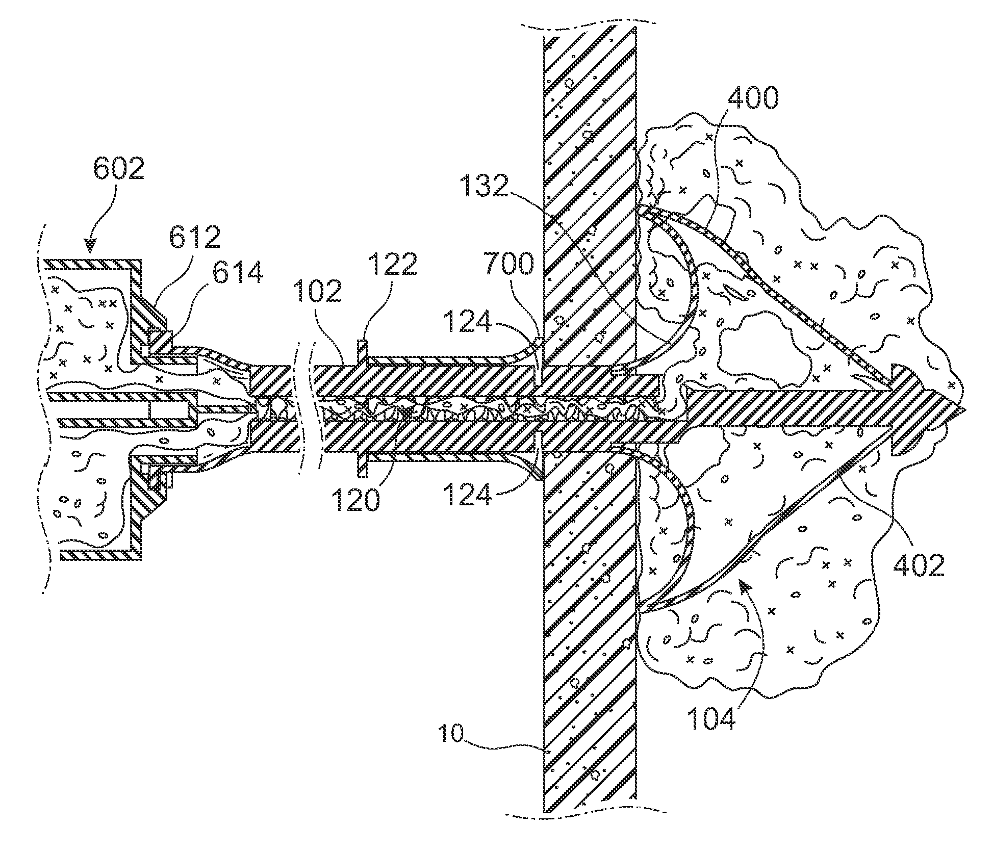
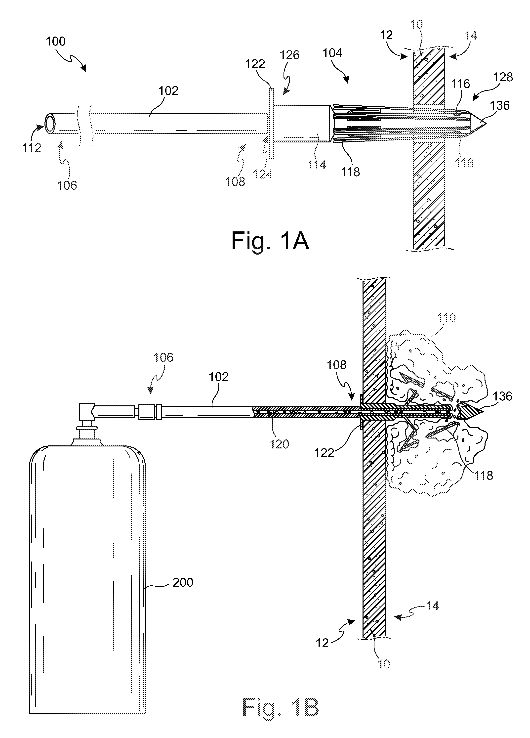
[0033]As shown in the Figures, the anchoring device 100 is designed to be insertable into a wall 10 through a first side 12, and held in place by an anchor 104 on the opposite side 14 to deliver a securing compound 110 to the opposite side 14 of the wall 10 and secure the anchor 104 to the wall 10. The securing compound may be initially flu...


PUM

PropertyMeasurementUnit
Lengthaaaaaaaaaa
Shapeaaaaaaaaaa

Abstract

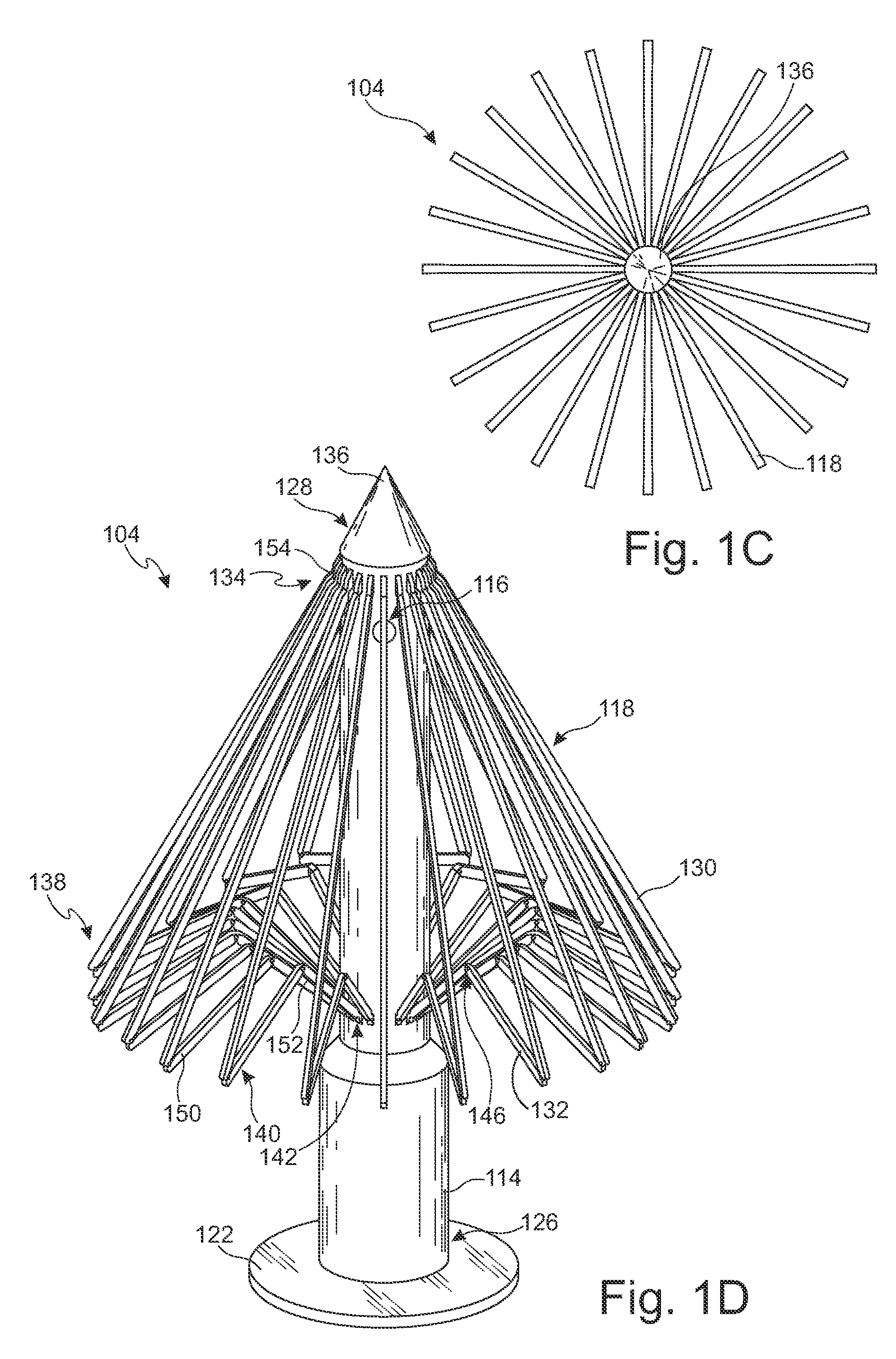
An anchoring device comprising a hollow shaft having a first end and a second end, and an anchor attached to the second end, wherein the anchor comprises a plurality of flukes to secure the anchoring device to a wall and at least one hole in fluid communication with the shaft to deliver a securing compound injected into the first end of the shaft to the flukes to facilitating securing the anchoring device to the wall. The flukes may be bendable or hingedly attached to the base of the anchor so as to accommodate a closed configuration to be insertable into a hole in the wall and expandable into an open configuration to prevent the anchoring device from being removed from the wall.

Description

CROSS-REFERENCE[0001]This patent application claims the benefit of U.S. Provisional Patent Application No. 61 / 255,787, filed Oct. 28, 2009, entitled “Wall Anchor,” which application is incorporated in its entirety here by this reference.BACKGROUND OF THE INVENTION[0002]1. Technical Field[0003]This invention relates to an anchoring device for walls, such as drywalls.[0004]2. Background Art[0005]The present invention is directed towards an anchoring device to improve the structural integrity of existing walls, such as drywalls. Current anchoring devices require unnecessary tubing or balloons. Others require complicated shapes or designs. Some require multiple steps, while others utilize devices that do not have the proper strength to provide the necessary support.[0006]Thus, there is a need for an anchoring device that can quickly, efficiently, and effectively provide support to a wall without the use of complicated devices and unnecessary steps.BRIEF SUMMARY OF INVENTION[0007]The anc...

Claims


Application Information

Patent Timeline
IPC IPC(8): E04B1/38
CPCF16B13/0833F16B13/141Y10T29/49938Y10T29/49966Y10T29/49947
Inventor HANRATTY, BRENT
Owner HANRATTY BRENT
Why Eureka
Try Eureka