
Multiple Layer Polymer Interlayers Having a Melt-Fractured Surface

a polymer interlayer and melt-fractured surface technology, applied in the direction of lamination, thin material processing, synthetic resin layered products, etc., can solve the problems of multi-layer interlayers, optical distortion, etc., and achieve the effect of not affecting optical distortion

Active Publication Date: 2011-04-28
SOLUTIA INC
View PDF66 Cites 7 Cited by
  • Summary
  • Abstract
  • Description
  • Claims
  • Application Information

AI Technical Summary

Benefits of technology

[0009]The present invention provides multiple layer interlayers having a soft inner polymer layer and relatively stiff outer layers that can be laminated without unacceptable optical distortion and used in various multiple layer glass panel type applications.
[0010]Multiple layer interlayers of the present invention have surface topography that is formed by controlling the melt fracture that occurs at the exposed surface of the interlayer, or individual layers of the multiple layer interlayer, during formation of the interlayer. By precisely controlling the surface topography of the interlayer, lamination of the interlayer with a rigid substrate does not lead to unacceptable optical distortion caused by the transfer of the surface topography through outer, stiffer layers into softer, internal layers of the interlayer.

Problems solved by technology

A particular problem encountered with multiple layer interlayers arises at the lamination stage of processing.
While single layer interlayers have conventionally been embossed with rollers to impart a texture that facilitates deairing, three layer interlayers having a relatively soft inner layer between two relatively stiffer layers, such as is found in some acoustic interlayers, will develop optical distortion if embossing of the outer surfaces of the interlayer is transferred to the inner, softer layer.

Method used


Image

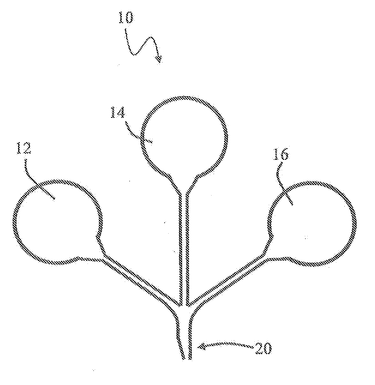
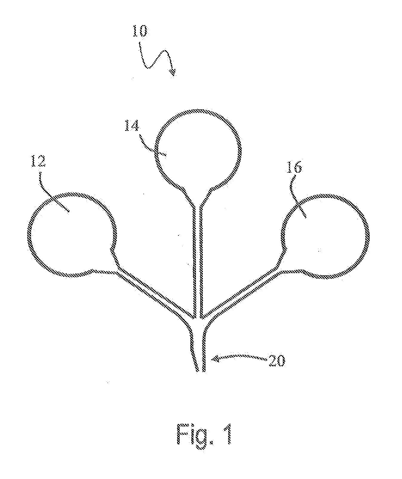
  • Multiple Layer Polymer Interlayers Having a Melt-Fractured Surface
  • Multiple Layer Polymer Interlayers Having a Melt-Fractured Surface
  • Multiple Layer Polymer Interlayers Having a Melt-Fractured Surface

Examples


example 1

[0087]Three three-layer interlayers are separately coextruded. Each interlayer comprises a 0.1524 millimeter (6 mil) layer sandwiched between two 0.3302 millimeters (13 mil) layers for a total thickness of 0.8128 millimeters (32 mils). The inner layer comprises 75 phr plasticizer (triethylene glycol di-(2-ethylhexanoate)) and 11.0% residual poly(vinyl alcohol), while the outside layers comprise 38 phr plasticizer (triethylene glycol di-(2-ethylhexanoate)) and 18.5% residual poly(vinyl alcohol).

[0088]Surface characteristics of the three layers are controlled during coextrusion with 30 melt fracture to provide differing levels of Rsm and Rz. Mottle, Rsm, and Rz for each interlayer is determined according to the procedure provided elsewhere herein. Rsm and Rz are the machine direction values (cross machine direction values are lower).

MottleSide 1,GradeRSMSide 2, RSMSide 1 RZSide 2 RZ270969441.135.5499999637.835.651008105454.855.4

[0089]By virtue of the present invention, it is now possi...


PUM

PropertyMeasurementUnit
coincident frequencyaaaaaaaaaa
temperatureaaaaaaaaaa
thicknessaaaaaaaaaa

Abstract

The present invention provides multiple layer interlayers having a soft inner polymer layer and relatively stiff outer layers that can be laminated without unacceptable optical distortion and used in various multiple layer glass panel type applications. Multiple layer interlayers of the present invention have surface topography that is formed by controlling the melt fracture that occurs at the exposed surface of the interlayer, or individual layers of the multiple layer interlayer, during formation of the interlayer. By precisely controlling the surface topography of the interlayer, lamination of the interlayer with a rigid substrate does not lead to unacceptable optical distortion caused by the transfer of the surface topography through outer, stiffer layers into softer, internal layers of the interlayer.

Description

CROSS REFERENCE TO RELATED APPLICATION(S)[0001]This application is a Divisional of U.S. patent application Ser. No. 11 / 734,797 filed Apr. 13, 2007 and currently pending, the entire disclosure of which is herein incorporated by reference.BACKGROUND[0002]1. Field of the Invention[0003]The present invention is in the field of polymer interlayers and multiple layer glass panels comprising polymer interlayers, and, more specifically, the present invention is in the field of polymer interlayers comprising multiple thermoplastic polymer layers.[0004]2. Description of the Related Art[0005]Poly(vinyl butyral) (PVB) is commonly used in the manufacture of polymer layers that can be used as interlayers in light-transmitting laminates such as safety glass or polymeric laminates. Safety glass often refers to a transparent laminate comprising a poly(vinyl butyral) layer disposed between two sheets of glass. Safety glass often is used to provide a transparent barrier in architectural and automotive...

Claims


Application Information

Patent Timeline
Patent Type & Authority Applications(United States)
IPC IPC(8): B32B37/04B29C47/06B32B37/24B29C65/70B29C48/08B29C48/17B29C48/21
CPCB29C47/0021B32B17/10935B29C47/043B29C47/065B29K2023/12B29K2027/06B29K2029/04B29K2067/00B29K2069/00B29K2075/00B29K2077/00B29K2105/0026B29K2105/0032B29K2105/0038B29K2105/0044B29L2009/00B32B17/10577B32B17/10761B32B7/12B32B17/1055B29C47/0057B32B27/06B32B27/22Y10T428/31909Y10T428/3163Y10T428/31859B29C48/08B29C48/21B29C48/17B29C48/0018B32B27/30C03C27/10
Inventor BOURCIER, DAVID PAULD'ERRICO, JOHN JOSEPHETIENNE, JEAN-PIERREMATIS, GARY
Owner SOLUTIA INC
Learn More