Variable directional microphone assembly and method of making the microphone assembly

Inactive Publication Date: 2011-04-28
BSE CO LTD
View PDF8 Cites 8 Cited by
  • Summary
  • Abstract
  • Description
  • Claims
  • Application Information

AI Technical Summary

Benefits of technology

[0009]The variable directional microphone according to the present invention can achieve miniaturization and improve sound quality according to the formation of acoustic space, by mounting the microphone devices in a compact structure with the

Problems solved by technology

), so that mechanical configuration for supplementing sound characteristics ar

Method used


Image

  • Variable directional microphone assembly and method of making the microphone assembly
  • Variable directional microphone assembly and method of making the microphone assembly
  • Variable directional microphone assembly and method of making the microphone assembly

Examples


Example

DESCRIPTION OF THE SYMBOLS IN MAIN PORTIONS OF THE DRAWINGS

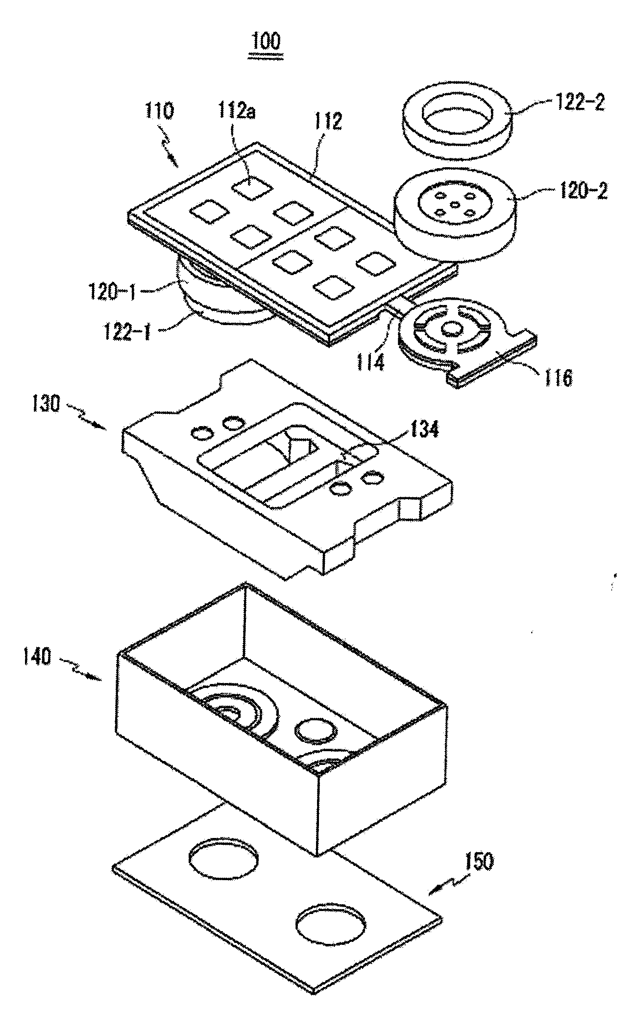
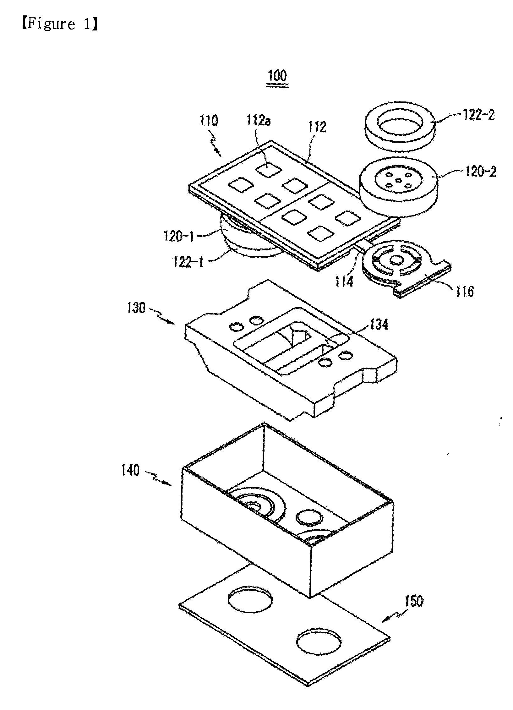
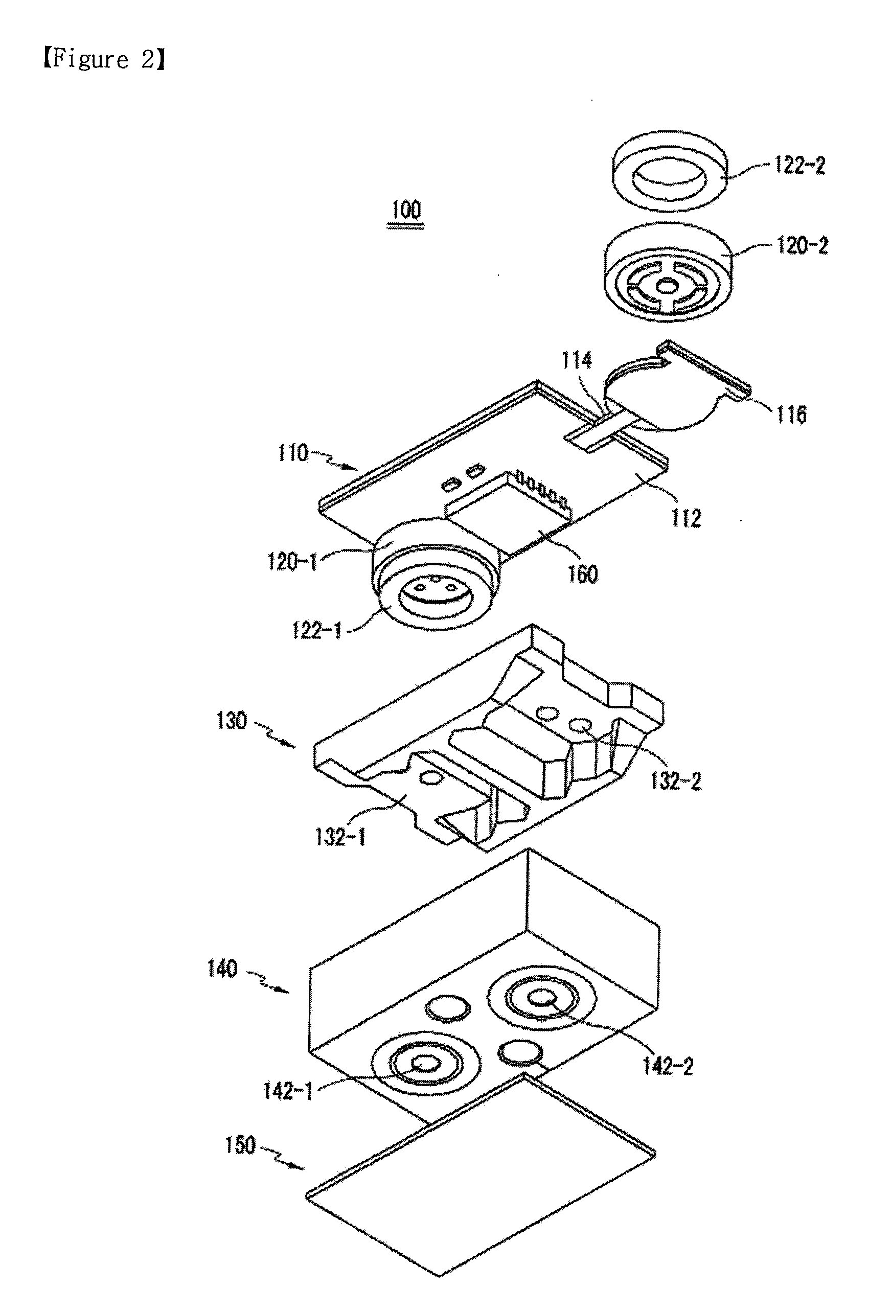
[0016]100: VARIABLE DIRECTIONAL MICROPHONE ASSEMBLY[0017]110: SUBSTRATE[0018]112: RIGID PRINTED CIRCUIT BOARD PART[0019]114: CONNECTION[0020]116: PRINTED CIRCUIT BOARD PART FOR MICROPHONE MOUNTING[0021]120-1, 120-2: MICROPHONE DEVICE[0022]122-1, 122-2: CUSHION[0023]130: MICROPHONE BODY[0024]132-1, 132-2: MOUNTING SPACE FOR MICROPHONE[0025]134: MOUNTING SPACE FOR SEMICONDUCTOR DEVICE[0026]140: CASE[0027]142-1, 142-2: SOUND HOLE[0028]150: DUST-PREVENTION FABRIC[0029]160: SEMICONDUCTOR INTEGRATED CIRCUIT DEVICE

BEST MODE

[0030]Preferred embodiments of the present invention will be described below in more detail with reference to the accompanying drawings. The present invention may, however, be embodied in different forms and should not be constructed as limited to the embodiments set forth herein.

[0031]FIG. 1 is an exploded perspective view illustrating a top side of a variable directional microphone assembly 100 according to an ...


PUM


Abstract

A variable directional microphone assembly and method of manufacturing the variable directional microphone assembly which includes a substrate, a semiconductor integrated circuit device, two microphone devices, a microphone body, and a case.

Description

TECHNICAL FIELD[0001]The present invention relates to a variable directional microphone, and more particularly, to a variable directional microphone assembly and a method of manufacturing the variable directional microphone assembly, which achieve miniaturization and improve sound quality, by mounting microphone devices provided to printed circuit board parts for microphone-mounting and connected with a flexible printed circuit board (FPCB), in a compact structure with a microphone body.BACKGROUND ART[0002]Microphones are generally classified into a non-directional (whole directions) microphone and a direct ional microphone according to directional characteristics. Such directional microphones are classified into a bi-directional microphone and a uni-directional microphone. The bi-directional microphone exhibits faithful reproduction characteristics for front and rear incident sounds, but exhibits reduction characteristics for a lateral incident sound. Thus, a polar pattern of the b...

Claims


Application Information

Patent Timeline
IPC IPC(8): H04R1/20
CPCH04R31/00H04R1/406H04R1/32
Inventor LEE, DONG-SUNKIM, HYOUNG-JOO
Owner BSE CO LTD
Why Eureka
Try Eureka