Image forming apparatus with developing units having different voltage levels

a technology of developing units and developing voltages, applied in the field of image forming apparatus, can solve the problems of deterioration of color image quality, difficult control of developing voltage levels by each developing device at a desired voltage level, and inability to adjust components related to the zener voltage of the zener diode, etc., to achieve the effect of reducing the deviation of developing voltages of respective developing units and improving color image quality

Active Publication Date: 2011-04-28
HEWLETT PACKARD DEV CO LP
View PDF9 Cites 5 Cited by
  • Summary
  • Abstract
  • Description
  • Claims
  • Application Information

AI Technical Summary

Benefits of technology

[0013]Therefore, it is an aspect of at least one embodiment to provide an image forming apparatus which changes an installation position of a Zener diode that forms a difference in potential between the developing bias voltage and the supply bias voltage of each developing unit to improve a color image quality, thereby reducing respective developing units' developing voltage deviation caused by a deviation of Zener diode components.

Problems solved by technology

However, these Zener diode components are generally installed at the last end serving as an output side that provides the developing roller and the supply roller of each developing device, so that it is impossible to adjust a deviation of components related to the zener voltage of the Zener diode.
For example, if the source voltage provided to each developing device is adjusted to provide a voltage (in which a deviation of components of the Zener diode corresponding to the yellow (Y) developing device is considered) to a yellow (Y) developing device, a deviation of several tens of volts occurs in voltage applied to other developing devices, so that it is difficult for each developing device to control a developing voltage level at a desired voltage level.
In other words, due to a deviation of Zener diode components that form a difference in potential between the developing bias voltage and the supply bias voltage, it is difficult for individual developing devices to acquire their desired color images, resulting in a deterioration of the color image quality.

Method used


Image

  • Image forming apparatus with developing units having different voltage levels
  • Image forming apparatus with developing units having different voltage levels
  • Image forming apparatus with developing units having different voltage levels

Examples


Embodiment Construction

[0040]Reference will now be made in detail to at least one embodiment, examples of which are illustrated in the accompanying drawings, wherein like reference numerals refer to like elements throughout.

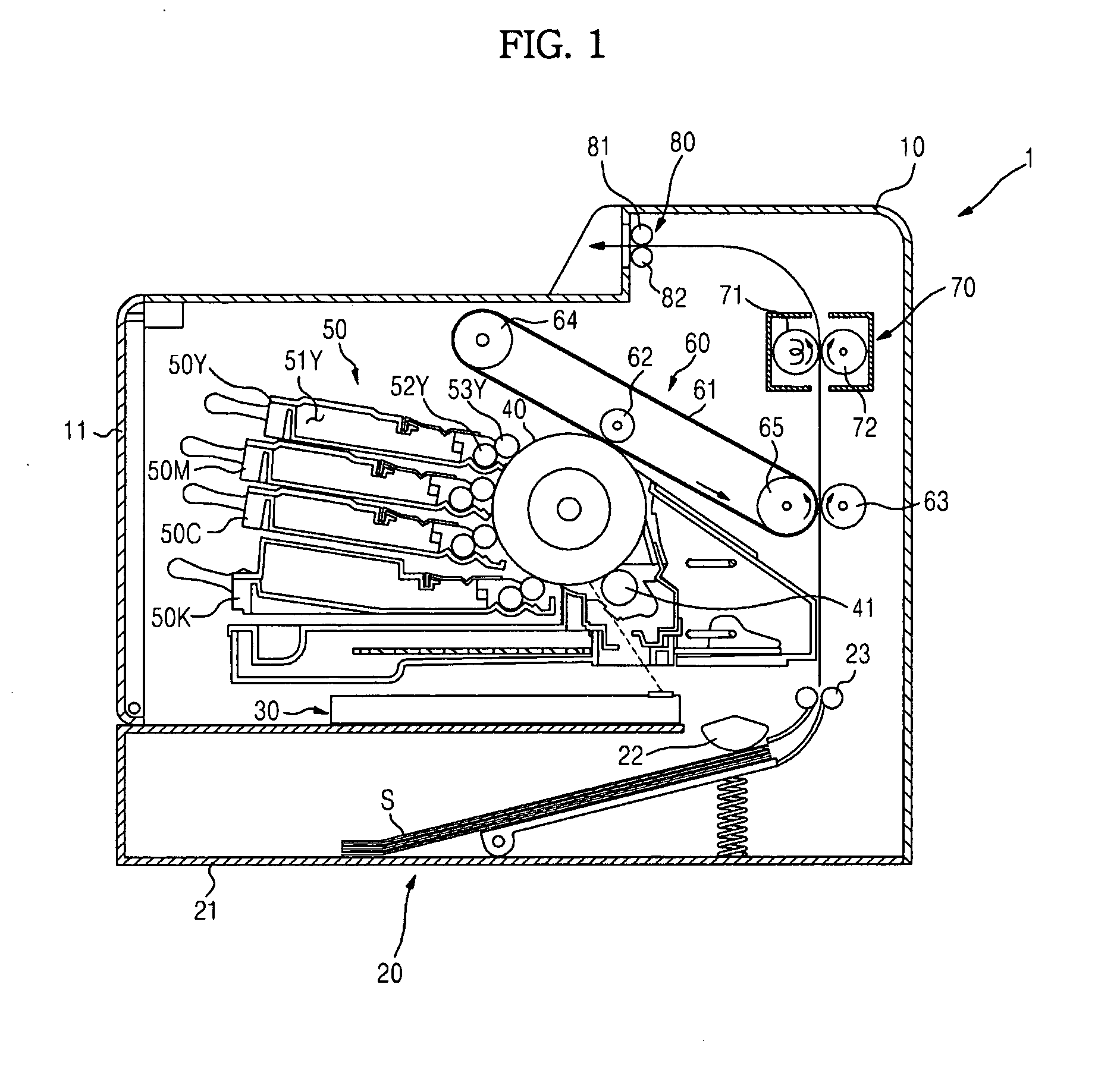
[0041]FIG. 1 is a structural diagram illustrating an image forming apparatus according to at least one exemplary embodiment.

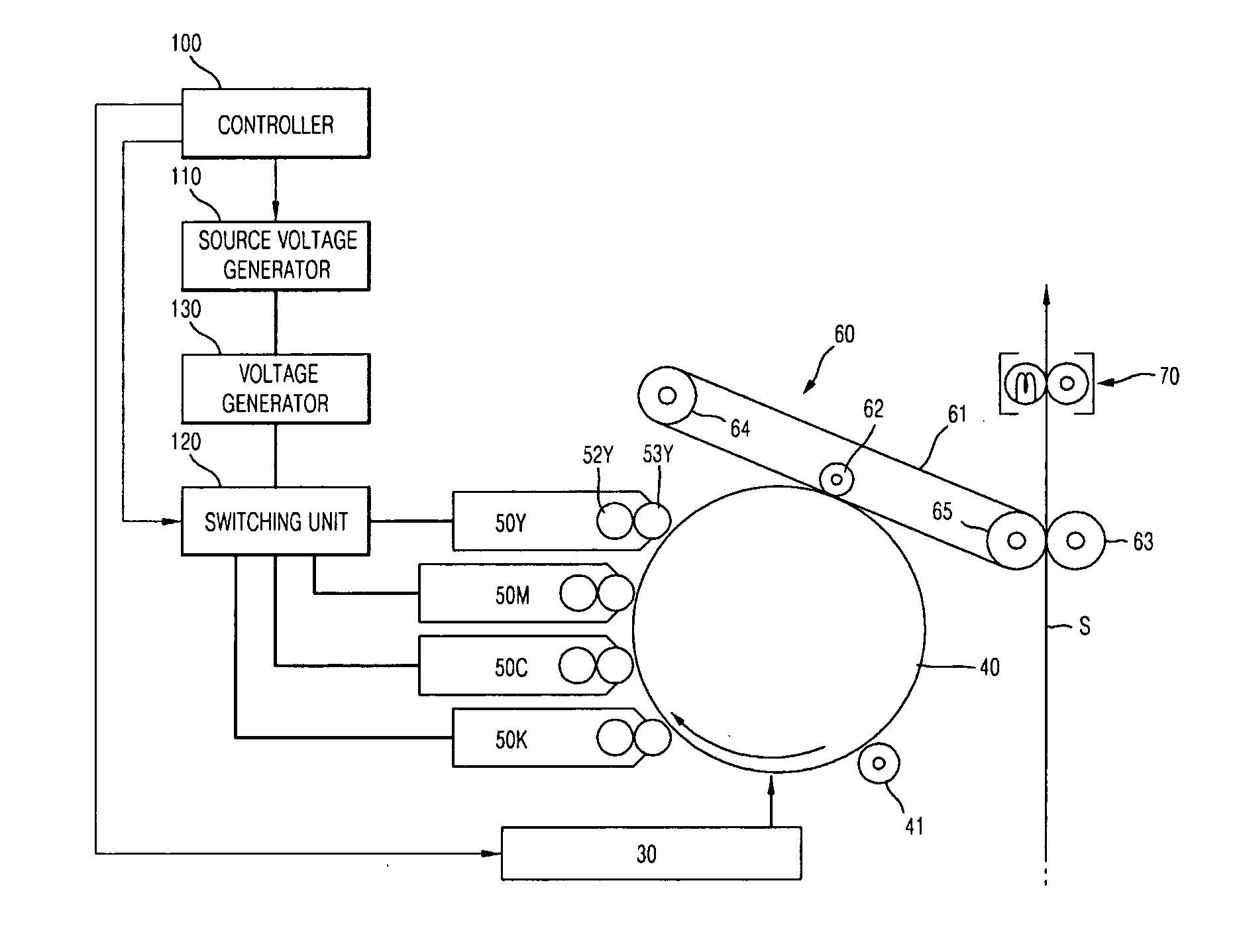
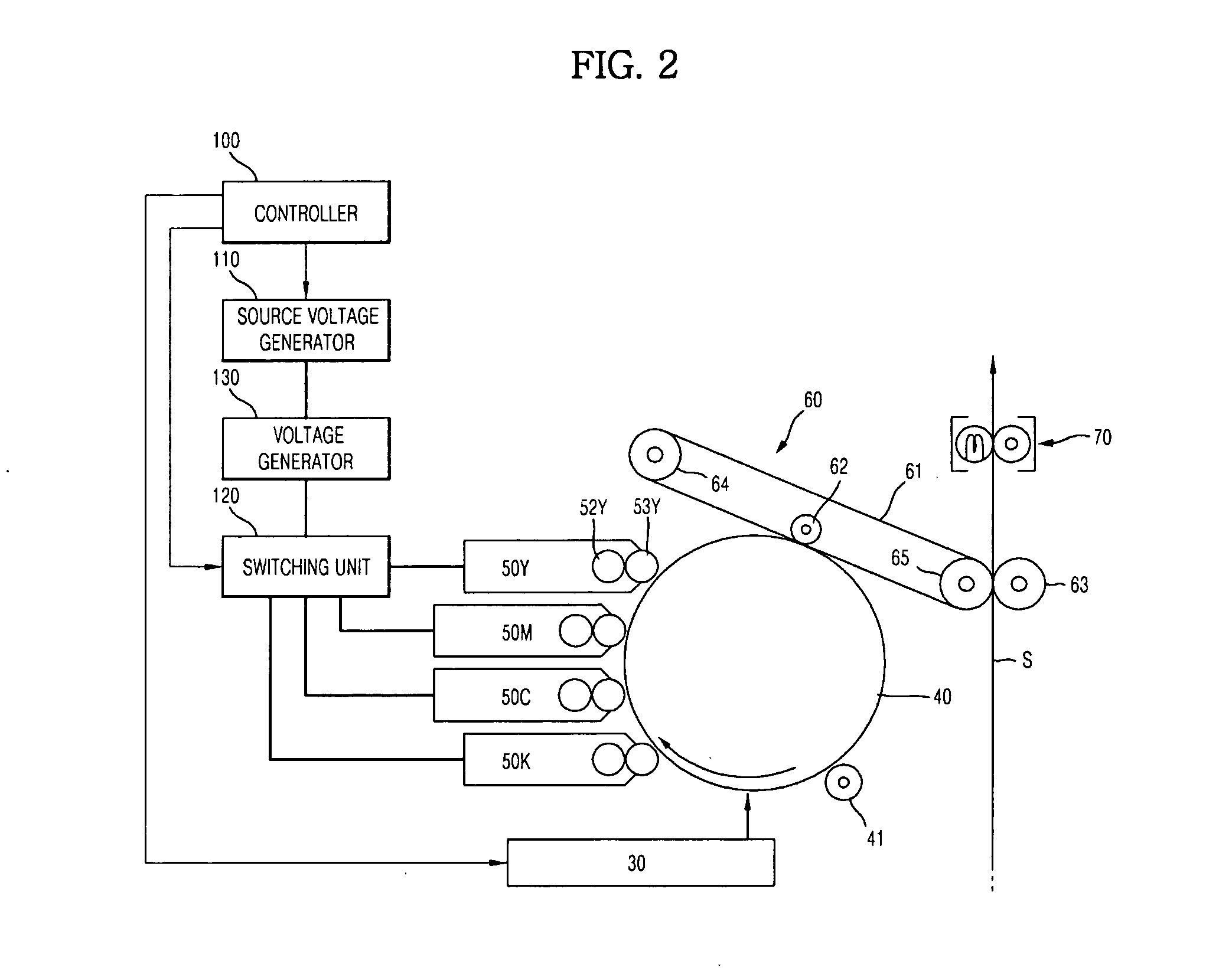
[0042]Referring to FIG. 1, the image forming apparatus 1 according to the at least one exemplary embodiment includes a main body 10, a printing medium feeder 20, a light scanning unit 30, a photoconductive drum 40, a developing device 50, a transfer unit 60, a fixing unit 70, and a printing medium discharger 80.

[0043]The main body 10 forms the external appearance of the image forming apparatus 1, and supports a variety of components installed in the image forming apparatus. A main body cover 11 is rotatably installed at one end of the main body 10. The cover 11 opens or closes some parts of the main body 10.

[0044]The printing medium feeder 20 feeds a printing medi...


PUM


Abstract

An image forming apparatus is disclosed. Zener diode separately installed to correspond to each developing device so as to form a difference in potential between the developing bias voltage and the supply bias voltage of each developing device, is installed at a common end, so that a deviation of the developing voltage applied to the developing device affected by a deviation of Zener diode components can be reduced, resulting in an increased color image quality. In addition, the Zener diode is installed in a common end, such that the number of Zener diodes is reduced, resulting in a reduction in production costs.

Description

CROSS-REFERENCE TO RELATED APPLICATIONS[0001]This application claims the priority benefit of Korean Patent Applications Nos. 2009-0101548 filed on 26 Oct. 2009 and 2010-0084496 filed on 31 Aug. 2010 in the Korean Intellectual Property Office, the disclosures of which are incorporated herein by reference.BACKGROUND[0002]1. Field[0003]At least one embodiment relates to an image forming apparatus including a plurality of developing devices that use the electrophotographic scheme.[0004]2. Description of the Related Art[0005]Generally, an electrophotographic printer forms an electrostatic latent image by scanning light onto a photoconductive drum charged with a predetermined potential, develops the electrostatic latent image with toners of predetermined colors, and transfers and fixes the developed image onto a sheet of paper, such that a color image is formed.[0006]In order to print a full-color image, the colors yellow (Y), magenta (M), cyan (C), and black (K) are required for the imag...

Claims


Application Information

Patent Timeline
Patent Type & Authority Applications(United States)
IPC IPC(8): G03G15/06
CPCG03G15/065G03G15/01G03G15/0121G03G15/80
Inventor EOM, YOON SEOP
Owner HEWLETT PACKARD DEV CO LP
Why Eureka
Try Eureka