Eureka AIR delivers breakthrough ideas for toughest innovation challenges, trusted by R&D personnel around the world.

Method of Fabricating a Chair

Active Publication Date: 2011-05-05
KNOLL INC
View PDF28 Cites 5 Cited by
  • Summary
  • Abstract
  • Description
  • Claims
  • Application Information

AI Technical Summary

Benefits of technology

[0009]A method of fabricating a chair is provided. The method includes the steps of providing a substrate and providing at least one female fastener device. The substrate may have a first side and a second side opposite the first side. The at least one female fastener device may include a body and a plurality of projections attached to the body. A portion of the body may define a channel that is sized and configured to receive a male fastener device. Each projection includes a distal end. The one or more female devices may be inserted into the substrate for attaching the at least one female fastener device to the substrate such that at least a portion of th

Problems solved by technology

However, the use of T-nuts often creates problems when used in conjunction with manufacturing chair components that are relatively thin, such as seat skins or back skins.
If the thickness of the structure to which the T-nut or other fastener device is attached is not sufficient, then the T-nut can become displaced, loosened or separated from the structure when a fastener is inserted into the opening of the T-nut.
The force exerted by the screwing of the screw in the opening can cause the T-nut to rotate and become dislodged from the structure if the barbs of the T-nut are not attached to a sufficiently thick structure.
Of course, such dislodgements may only occur intermittently during fabrication as a result of changes in structure dimensions due to tolerance control problems or may only act to loosen the T-nut from a structure.
If such dislodgements go undetected during chair manufacturing, the dislodgments can create a problem for a chair purchaser.
For instance, such a chair may require maintenance shortly after being purchased.
Such problems can reduce the goodwill of the chair provider and can detract from the desirability of the chair.

Method used


Image

  • Method of Fabricating a Chair
  • Method of Fabricating a Chair
  • Method of Fabricating a Chair

Examples


Embodiment Construction

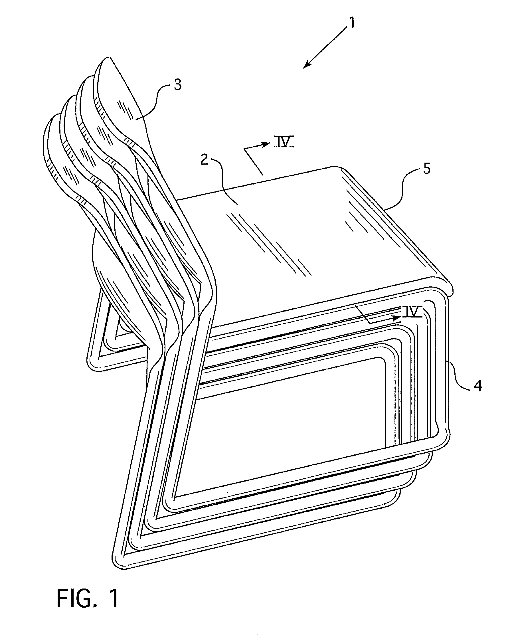
[0033]Referring to FIG. 1, a chair 1 may include a seat 2 and a back 3. The seat and back components may be attached to a base 4. The chair may be designed to be stackable onto other chairs to form a stack 5 of chairs.

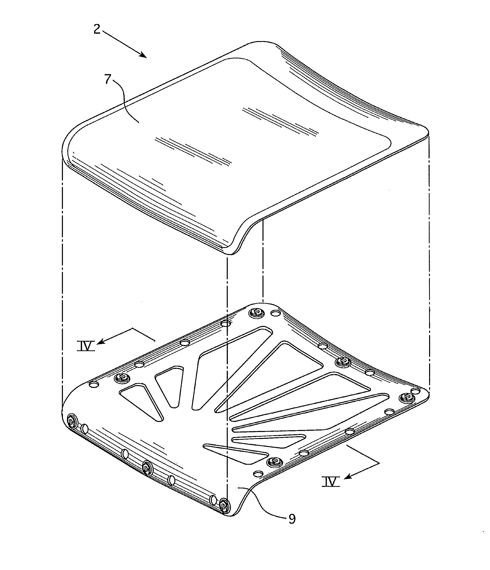
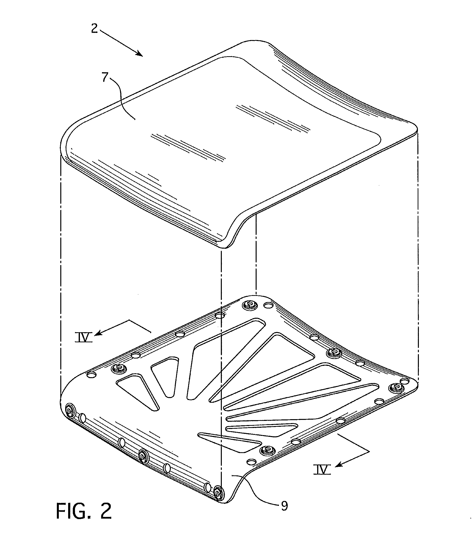
[0034]Referring to FIGS. 2-5, a seat 2 may include a covering 7 that includes a foam cushion that is attached to a substrate 9. Preferably, the substrate 9 is a relatively thin liner composed of plastic and is between 0.08 inches and 0.187 inches thick. The substrate may have a circular or curved shape or have a polygonal shape. The substrate may also be a structure that is molded of a polymeric material. For instance, the substrate may be seat pan, a polymeric sheet or a polymeric plate, that is relatively thin and extends over an area to at least partially define a portion of a seat assembly. As another example, the substrate may be a portion of a back frame assembly of a chair. As yet another example, the substrate 9 may be a portion of a seat frame that supports a ...


PUM

PropertyMeasurementUnit
Bending strengthaaaaaaaaaa
Polymericaaaaaaaaaa

Abstract

A method of making a chair includes the steps of providing at least one female fastener device. The at least one female fastener device is inserted into a substrate for attaching the at least one female fastener device to the substrate such that at least a portion of that female fastener device's body defining a channel extends into the substrate and the projections extend through the substrate such that the distal ends of the projections extend beyond a second side of the substrate that is opposite a first side of the substrate. The distal ends of the projections are bent into the second side of the substrate. At least one male fastener is inserted into the channel of the at least one female fastener device to attach a chair component to the substrate.

Description

CROSS REFERENCE TO RELATED APPLICATIONS[0001]The present application claims priority to U.S. Provisional Patent Application No. 61 / 257,502, which was filed on Nov. 3, 2009. The entirety of U.S. Provisional Patent Application No. 61 / 257,502 is incorporated herein by reference.FIELD OF THE INVENTION[0002]The present invention relates to chairs and methods of making chairs.BACKGROUND OF THE INVENTION[0003]Chairs often include a seat or back. The seat or back can include a back frame or seat frame and a skin that covers the back frame or seat frame. The skins, particularly seat skins, can include a covering that covers foam attached to a liner or substrate affixed to a frame component. The foam of the skin may be welded or adhered or insert molded to the liner or substrate. The substrate or liner may then be attached to a frame component for attaching the seat skin to the frame. Screws, bolts, or other fasteners are often used to attach a frame component to a seat skin or back skin line...

Claims


Application Information

Patent Timeline
IPC IPC(8): A47C7/02B23P11/00
CPCA47C3/04A47C7/02Y10T29/49954Y10T29/49922A47C3/00
Inventor VAN HEKKEN, HENDRIK R.FERGUSON, JASON
Owner KNOLL INC
Why Eureka
Eureka Blog
Learn More