Holding structure for a touch panel

Inactive Publication Date: 2011-05-05
SMK CORP
View PDF2 Cites 46 Cited by
  • Summary
  • Abstract
  • Description
  • Claims
  • Application Information

AI Technical Summary

Benefits of technology

[0017]Since at least one of the peripheral edge of the touch panel and the peripheral edge of the opening of the casing is not bonded partly to the protective sheet, the damping of the vibration by the piezoelectric devices due to the bonding of the protective sheet with the touch panel is restricted and the holding structure for a touch panel related to the present invention can effectively demonstrate the force feedback function of the

Problems solved by technology

Even though the ITO films on the upper and the lower panel substrates get in contact with each other when an operator

Method used


Image

  • Holding structure for a touch panel
  • Holding structure for a touch panel
  • Holding structure for a touch panel

Examples


first embodiment

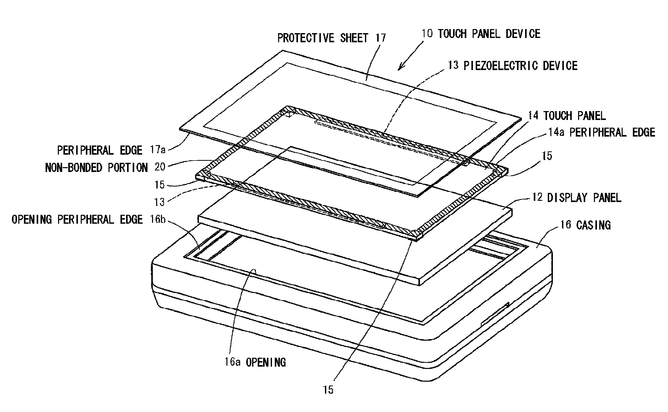
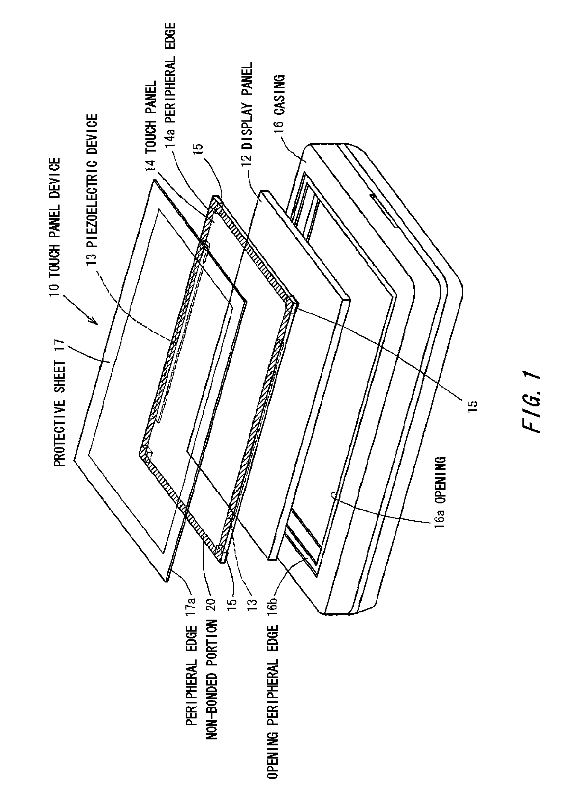
[0030]Hereinafter, the embodiments related to the present invention are to be explained based upon Figures. FIG. 1, FIG. 2, FIG. 3 and FIG. 4 show a first embodiment related to the present invention. The touch panel device 10 in the embodiment illustrates an embodiment used in a portable information terminal device. Moreover a touch panel is used in such various display panels as a computer display, a vehicle navigation device, an automated teller machine, a ticket vending machine serving as an input device. The touch panel device 10 is provided with a display panel 12 used for a liquid crystal display panel or an electroluminescence display panel or the like and a touch panel 14 for allowing an input operation, and has a casing 16 molded by resin or the like accommodating the display panel 12 and the touch panel 14. Furthermore, the casing 16 accommodates a circuit board, a power source unit or other electronic components, which are not illustrated here.

[0031]The structure of the t...

second embodiment

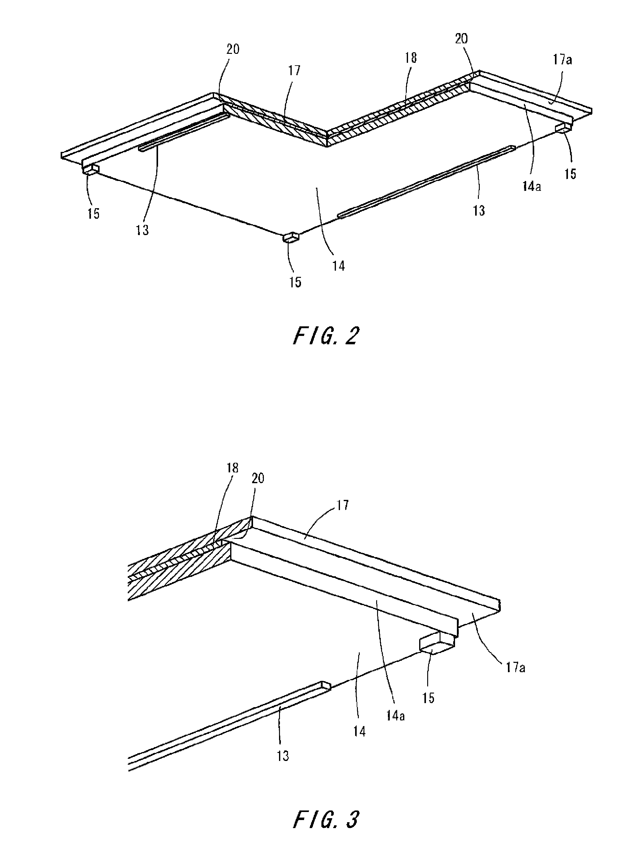
[0038]Hereinafter, the holding structure for a touch panel related to the present invention is to be explained based upon FIG. 5. Here, the same symbols are allocated to the same or the similar members appeared in the embodiments mentioned above and the explanation is omitted. In the touch panel 14 in accordance with the embodiment, a non-bonded portion 20 which is not provided with adhesive 18 is formed at a pair of sides of the peripheral edge 14a of the front surface of the touch panel 14. In this case, the pair of sides are disposed perpendicular to the pair of the sides at which the piezoelectric devices 13 are provided.

[0039]The embodiment also gives the similar effect as the embodiments mentioned above. In addition, the non-bonded portion 20 is allowed to be formed at a pair of sides of the peripheral edge 14a where the piezoelectric devices 13 are provided. The non-bonded portion 20 is allowed to be formed at one side of the peripheral edge 14a of the touch panel 14. The non...

third embodiment

[0040]Hereinafter, the holding structure for a touch panel related to the present invention is to be explained based upon FIG. 6. Here, the same symbols are allocated to the same or the similar members appeared in the embodiments mentioned above and the explanation is omitted. In the touch panel 14 in accordance with the embodiment, the non-bonded portion 20 is formed at the entire peripheral edge 14a of the touch panel 14. And also at the front surface side of the peripheral edge 16b of the opening of the casing 16, a portion bonded by the adhesive 19 at the entire peripheral edge 17a of the protective sheet 17 and a non-bonded portion 22 where no bonding is executed are provided to the entire periphery. In the embodiment, since the non-bonded portion 22 with the protective sheet 17 is formed at the peripheral edge 16b of the opening of the casing 16 in addition to the peripheral edge 14a of the touch panel 14, it is possible to give rise to the vibration of the touch panel 14 effe...


PUM


Abstract

A holding structure for a touch pane has a display panel for forming a display screen, a touch panel for allowing an input operation, a piezoelectric device for applying vibration to the touch panel in accordance with the operation of the touch panel, a casing for accommodating the display panel and the touch panel and a protective sheet having a size larger than the touch panel. The casing has an opening through which the touch panel is exposed. The protective sheet is applied to an entire front surface of the touch panel. The protective sheet has a non-bonded portion at a peripheral edge. The non-bonded portion is not bonded partly to at least one of a peripheral edge of the touch panel and a peripheral edge of the opening of the casing.

Description

CROSS REFERENCE TO RELATED APPLICATION[0001]The contents of the following patent applications are incorporated herein by reference,[0002]NO. 2009-252059 filed on Nov. 2, 2009,[0003]NO. 2009-259031 filed on Nov. 12, 2009, and[0004]NO. 2009-271579 filed on Nov. 30, 2009.BACKGROUND[0005]1. Technical Field[0006]This invention relates to a holding structure for a touch panel, which is provided to a display or an operation unit of a variety of electronic devices and being used as an input device.[0007]2. Description of the Related Art[0008]Conventionally, electronic devices having a touch panel function as input means at the display surface have been used widely. One of the structures of the touch panels was a resistance-sensitive type. In the resistance-sensitive touch panel, usually a transparent ITO (indium oxide) film is formed on the glass surface of the touch panel in a predetermined pattern. Electrodes are connected to the end portion of the ITO film and the peripheral edge is coat...

Claims


Application Information

Patent Timeline
IPC IPC(8): G06F3/041G06F3/0354
CPCG06F1/1626G06F1/1643G06F3/041G06F3/03547G06F3/016
Inventor IMAI, KAZUOIWAWAKI, SHINYAMIZUKI, TAKAYUKI
Owner SMK CORP
Why Eureka
Try Eureka