
Protector

Active Publication Date: 2013-07-04
SUZUKI MOTOR CO LTD
View PDF1 Cites 0 Cited by
  • Summary
  • Abstract
  • Description
  • Claims
  • Application Information

AI Technical Summary

Benefits of technology

The present invention is designed to provide a protector that can effectively restrict the vibration at the outer edge portion of each vehicle body cover part, even with a small number of coupling points. The protector helps to prevent abrasion between the vehicle body cover parts and unpleasant hammering noise, and increases the coupling strength between the vehicle body cover parts while securing rigidity even with a small number of coupling points. The connecting portion of the protector is fixed to the vehicle body cover part, effectively preventing the protector from falling off. Overall, the present invention suppresses vibration at the outer edge portion of each vehicle body cover part, even when the number of coupling points is small.

Problems solved by technology

With respect to such a vehicle body cover, since the vehicle body cover is divided into a plurality of parts, it is difficult to secure the rigidity of each vehicle body cover part.
The low rigidity of the vehicle body cover parts may cause vibration at the outer edge portion of each vehicle body cover part, resulting in causing of abrasion or unpleasant hammering noise between the parts.
In this case, although it may be conceivable to increase the number of coupling points of the vehicle body cover parts to secure the rigidity, it is difficult for a small vehicle body cover to provide a large number of coupling points.

Method used


Image

  • Protector
  • Protector
  • Protector

Examples


Embodiment Construction

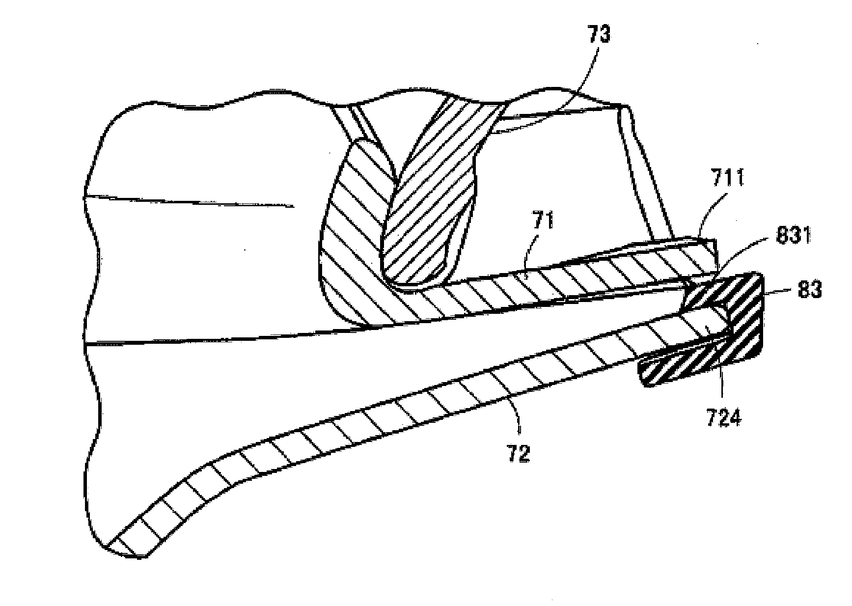
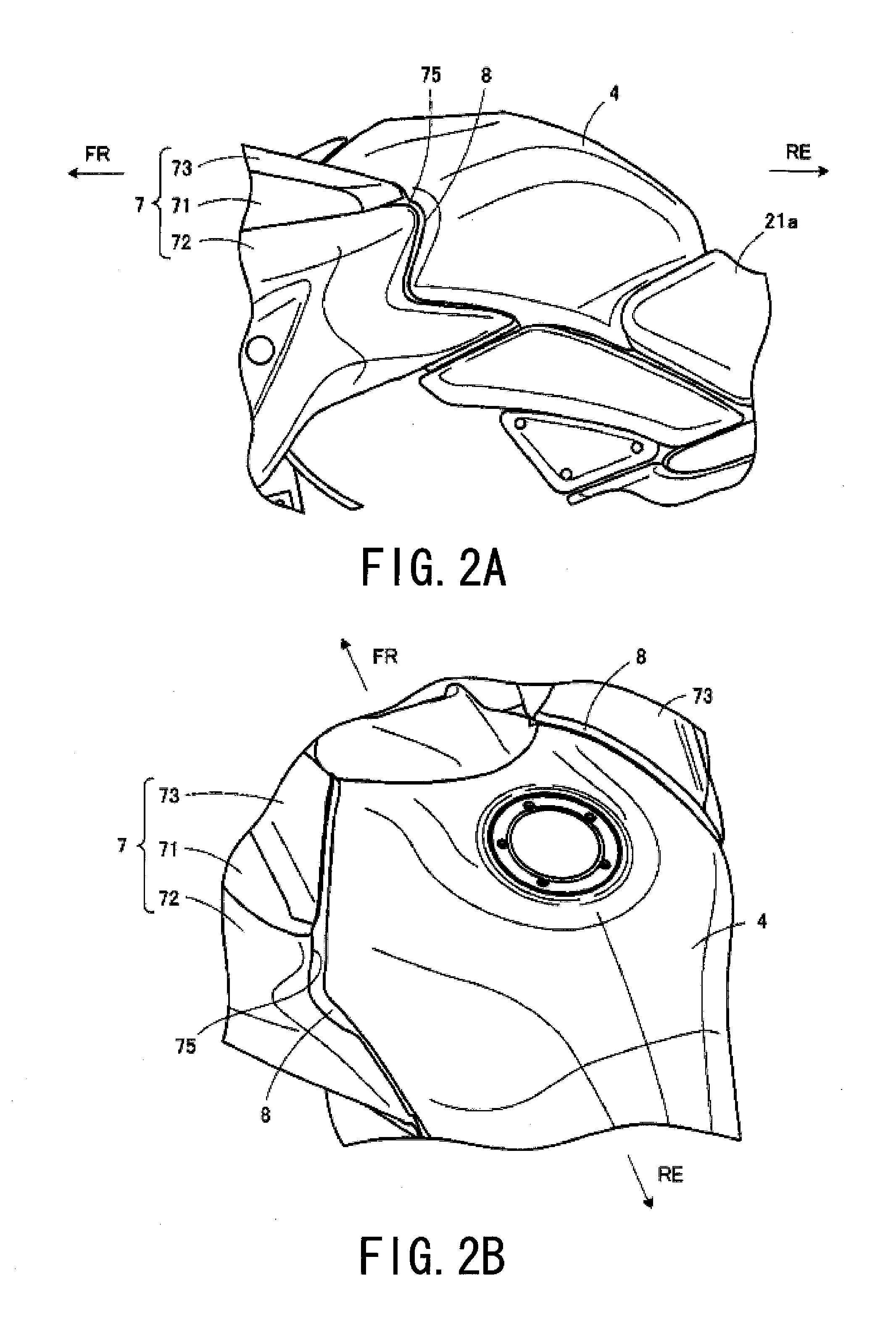
[0023]Hereinafter, a present embodiment will be described in detail with reference to the appended drawings.

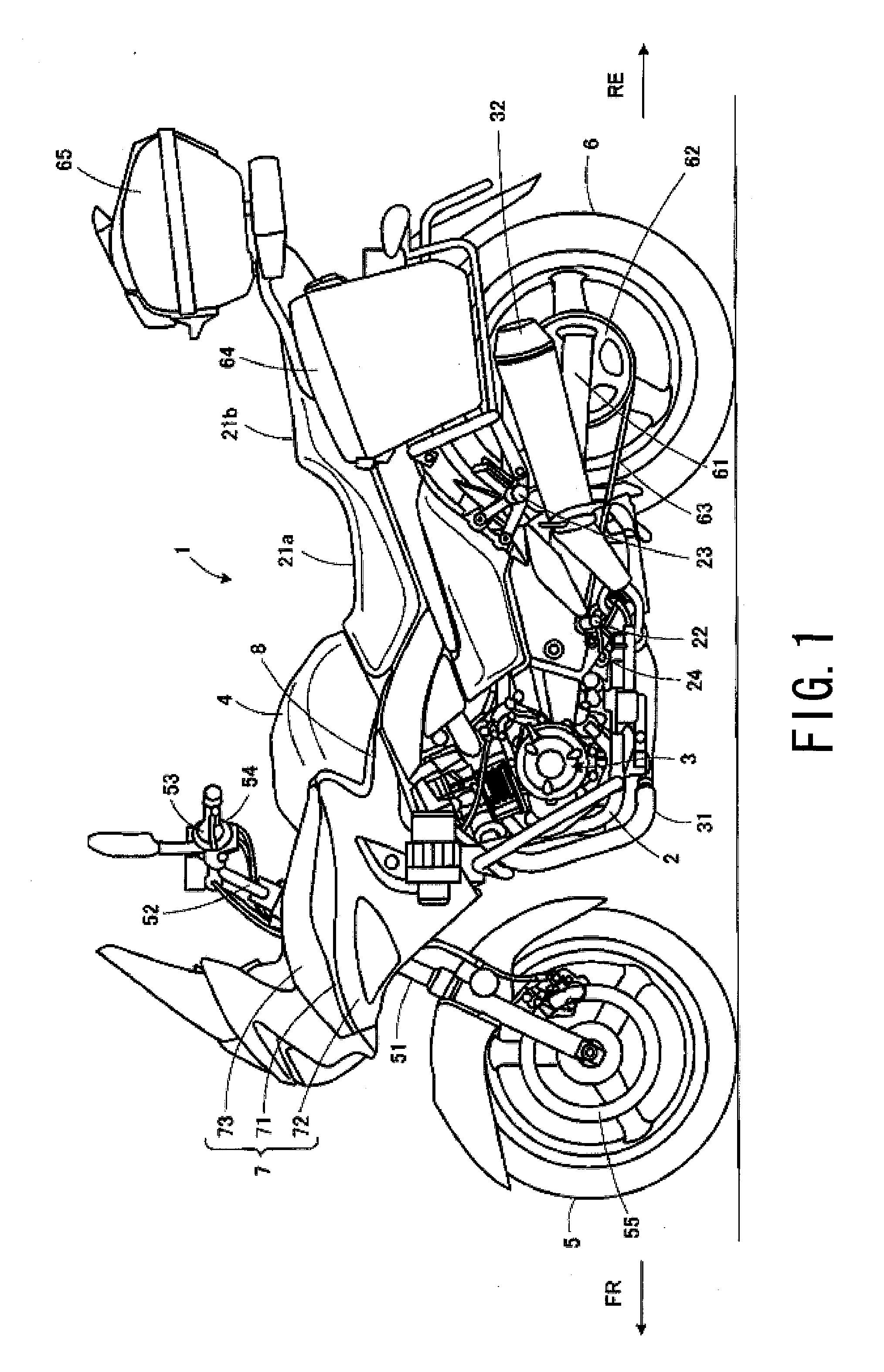
[0024]Further, it is to be noted that, in the following, an explanation will be given assuming a case where a protector of the present invention is applied to a touring motorcycle. However, the application target is not limited to the touring motorcycle and to be applicable to other types of motorcycles or saddle-type vehicles such as all-terrain vehicles (ATV).

[0025]It is further to be noted that terms “upper”, “lower”, “right”, “left” and like terms indicating directions will be used herein with reference to the illustrated states on the drawings or in a motorcycle standing state as shown in FIG. 1, and in addition, in the drawings, the front of a vehicle body is shown with an arrow FR, and the rear of the vehicle body is shown with an arrow RE.

[0026]First, an overall configuration of a motorcycle 1 according to the present embodiment will be described with reference to FIGS...


PUM


Abstract

A vehicle is provided with a protector for absorbing shock for a vehicle body cover to be attached to an outer edge portion of the vehicle body cover on an outer side of a vehicle body. The vehicle body cover is composed of a plurality of vehicle body cover parts which are coupled with each other so as to constitute the vehicle body cover, and the protector includes an attachment portion attached so as to straddle outer edge portions of adjacent vehicle body cover parts among a plurality of vehicle body cover parts.

Description

BACKGROUND OF THE INVENTION[0001]1. Field of the Invention[0002]The present invention relates to a protector for a vehicle body cover of a vehicle such as motorcycle, and more particularly, to a protector that is attached to a vehicle body cover of a saddle-type vehicle.[0003]2. Description of the Related Art[0004]As such conventional type of protector for a vehicle body cover, there is known a rubber mold to be attached to an outer edge portion of a vehicle body cover (for example, disclosed in Patent Document 1 (Japanese Utility Model Laid-Open No. 57-53989)). The rubber mold of Patent Document 1 has an attachment portion of a groove shape in a cross-section, and is formed to have a long shape so as to follow an outer edge portion of a vehicle body cover. The rubber mold protects the outer edge portion of the vehicle body cover by fitting an attachment groove to the outer edge portion of the vehicle body cover.[0005]Further, a naked-type motorcycle may have a small vehicle body co...

Claims


Application Information

Patent Timeline
IPC IPC(8): B62D27/04
CPCB62D27/04B62J23/00B62J17/02B62J17/00
Inventor MATSUSHITA, HIROKI
Owner SUZUKI MOTOR CO LTD
Learn More