
Self-service device comprising a surveillance unit

a self-service device and surveillance unit technology, applied in closed-circuit television systems, television systems, atm details, etc., can solve the problem of constantly looking around the user of cash dispensers, and achieve the effect of simple design and prevention of spying

Inactive Publication Date: 2011-05-05
WINCOR NIXDORF INT
View PDF10 Cites 3 Cited by
  • Summary
  • Abstract
  • Description
  • Claims
  • Application Information

AI Technical Summary

Benefits of technology

[0013]An object of the invention is to configure a self-service device of the type described in detail at the beginning in such a way that the surveillance unit or apparatus is simple in design but that it prevents spying with the greatest possible certainty.
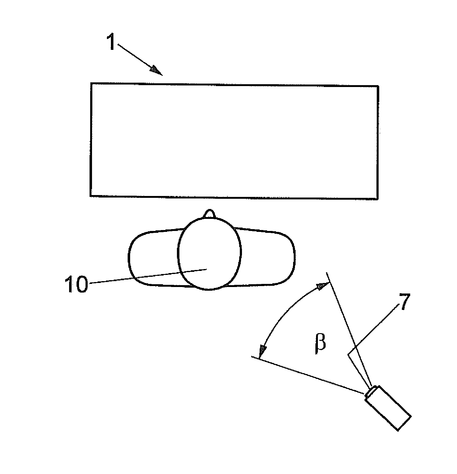
[0014]Since the surveillance apparatus is designed as a camera and the image from this camera is transmitted onto a screen in the area of the control panel, components can be used that are intrinsically known from video surveillance and have proved themselves in practice. Using the surveillance apparatus, the user of a self-service device, without having to look round or even having to change his line of sight, can constantly observe the area behind him and thereby detect unobtrusively any attempt to spy by a person behind him.
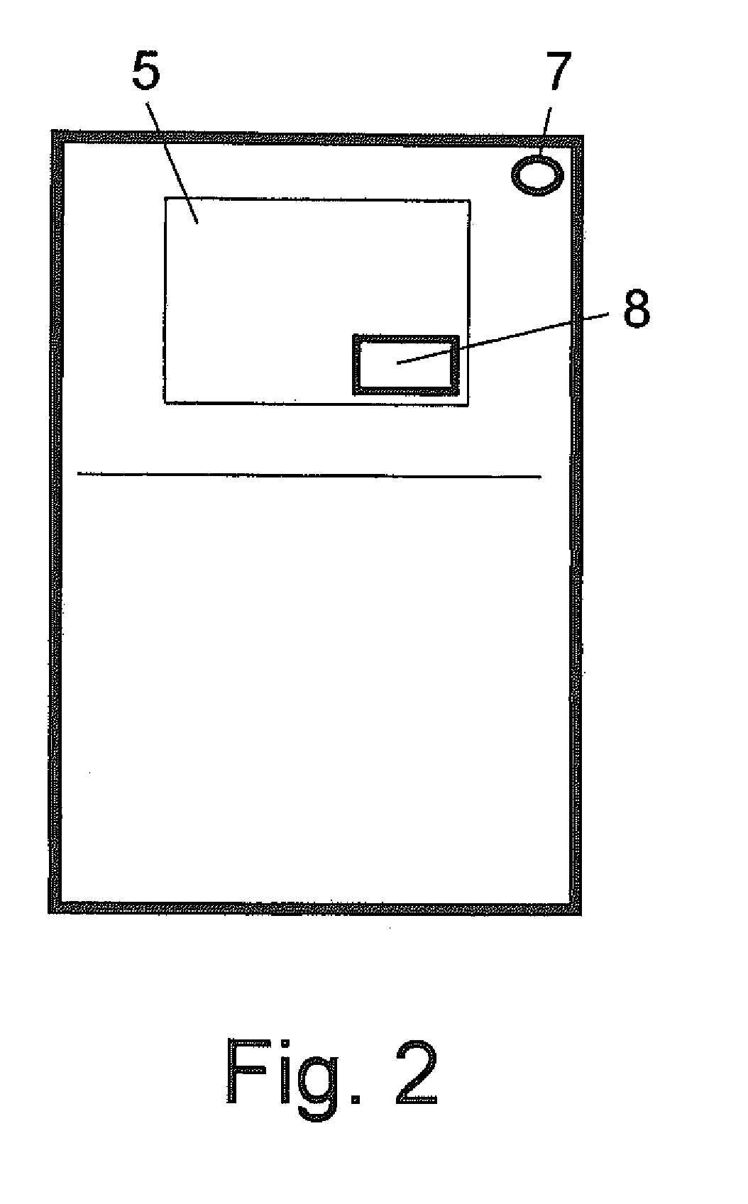
[0015]The intention is therefore for there to be precisely one screen in the control panel on which the informational or transaction data and the image from the camera can be displayed, specifically as an image-within-image representation. As a result, it is optimally possible for the user to obtain the information he wishes or to carry out a transaction and at the same time observe the area behind him.
[0016]In a preferred embodiment it is intended that the camera is installed to one side of the control panel in the basic housing of the self-service device. This is accomplished in a simple manner, so that the camera can see past the user into the area behind the user and the image recorded by the camera can be shown on the control panel screen for the user so that said user can at all times detect any attempt to spy by a person behind him without having to turn away from the screen to do so.

Problems solved by technology

The disadvantage of such visual protection overlays and keypads is that the user of a cash dispenser must constantly look around in order to ascertain whether a person standing behind him is trying to spy out his PIN number.

Method used


Image

  • Self-service device comprising a surveillance unit
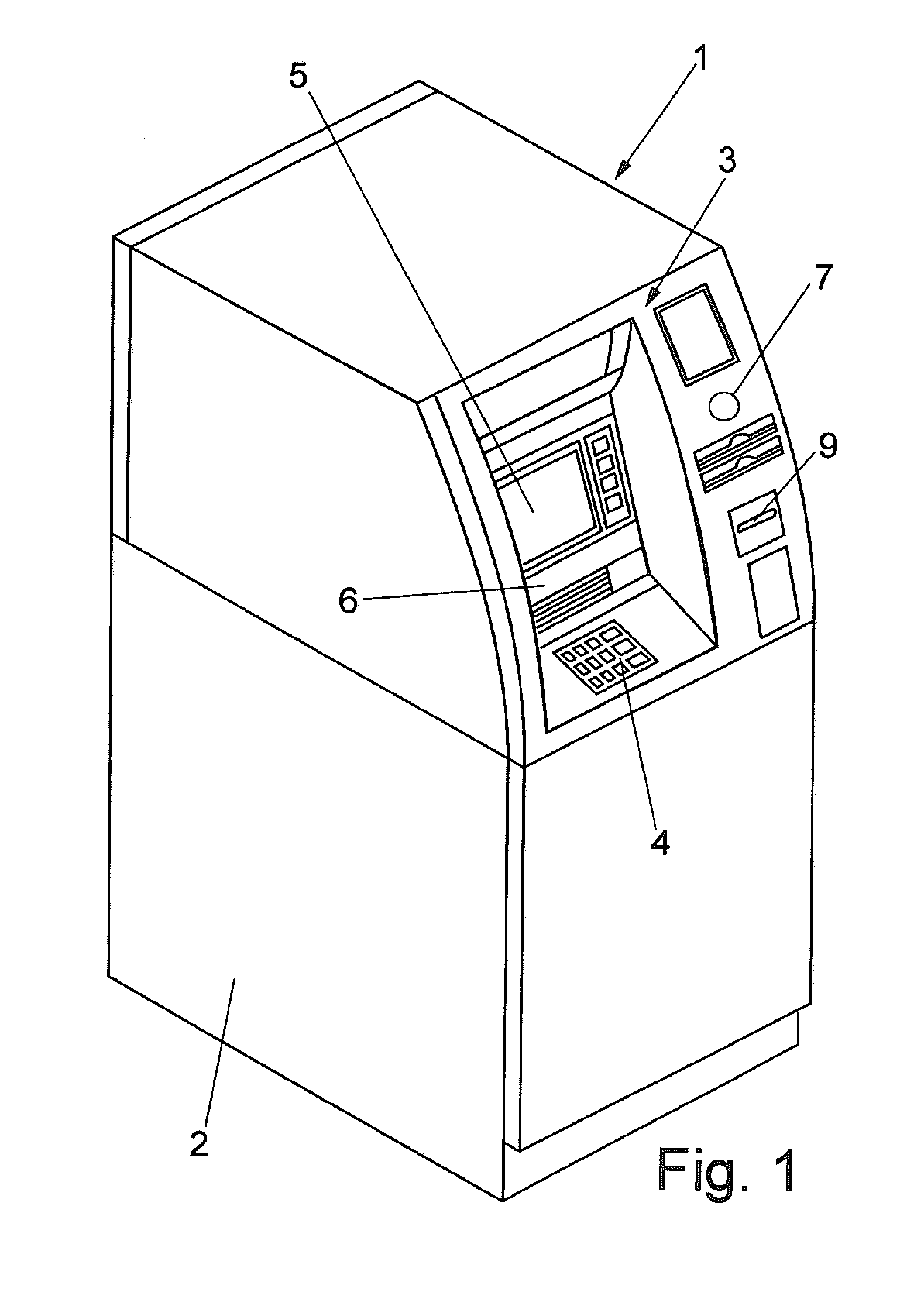
  • Self-service device comprising a surveillance unit
  • Self-service device comprising a surveillance unit

Examples


Embodiment Construction

[0025]Example embodiments will now be described more fully with reference to the accompanying drawings.

[0026]In the following description of the Figures, terms such as top, bottom, left, right, front, back etc. refer solely to the example depicted in the respective drawings and position of the self-service device and other parts. The terms are not be construed as restrictive, that is to say these references may change in different operating positions or as the result of a mirror-symmetrical layout or similar.

[0027]The self-service device shown in FIG. 1 is equipped with a basic cabinet 2. In the embodiment shown, a surveillance apparatus 7 is installed to the side of the operator with a control panel 3 in the upper area that is designed as a camera 7, specifically a live-image camera. The camera 7 is installed in the embodiment shown inside the basic housing 2, or rather the basic housing 2 is designed in such manner that the surveillance apparatus 7 lies within the basic housing 2....


PUM


Abstract

A self-service device (1), specifically a cash dispenser, account statement printer, and / or information or transaction terminal, having a basic housing (2), a control panel (3) with at least one screen (5) and one or more additional components (4, 6, 8, 9) and a surveillance apparatus (7), wherein the surveillance apparatus (7) is configured as a camera (7) and whose image information can be displayed on a screen (5) located in the area of the control panel (3), wherein the camera is located in such manner that an area behind a user of the self-service device (1) can be scanned.

Description

CROSS-REFERENCE TO RELATED APPLICATIONS[0001]This application is a National Stage of International Application No. PCT / EP2009 / 004626, filed Jun. 26, 2009. This application claims the benefit and priority of German application 10 2008 031 281.9, filed Jul. 2, 2008. The entire disclosures of the above applications are incorporated herein by reference.BACKGROUND[0002]This section provides background information related to the present disclosure which is not necessarily prior art.[0003]1. Technical Field[0004]The invention relates to a self-service device.[0005]2. Discussion[0006]Self-service devices of this type are known in the form of cash dispensers, for example, account statement printers and information or transaction terminals in widely different forms. The basic housing of a self-service device is designed in accordance with its particular purpose. The control panel is located in a position ergonomically favorable to the user. The components of the control panel may be, for exam...

Claims


Application Information

Patent Timeline
Patent Type & Authority Applications(United States)
IPC IPC(8): H04N7/18
CPCG07F19/207G07F19/20
Inventor HOLLAND-LETZ, GUENTER
Owner WINCOR NIXDORF INT
Learn More