Diffusion system for and automated luminaire

a technology of automatic luminaires and diffusers, applied in lighting applications, lighting apparatuses, entertainment, etc., can solve the problems of system limitation in both range and finesse of control

Inactive Publication Date: 2011-05-05
ROBE LIGHTING
View PDF5 Cites 8 Cited by
  • Summary
  • Abstract
  • Description
  • Claims
  • Application Information

AI Technical Summary

Problems solved by technology

Such a system may be limited in both its range and finesse of co

Method used


Image

  • Diffusion system for and automated luminaire
  • Diffusion system for and automated luminaire
  • Diffusion system for and automated luminaire

Examples


Embodiment Construction

[0011]Preferred embodiments of the present invention are illustrated in the FIGUREs, like numerals being used to refer to like and corresponding parts of the various drawings.

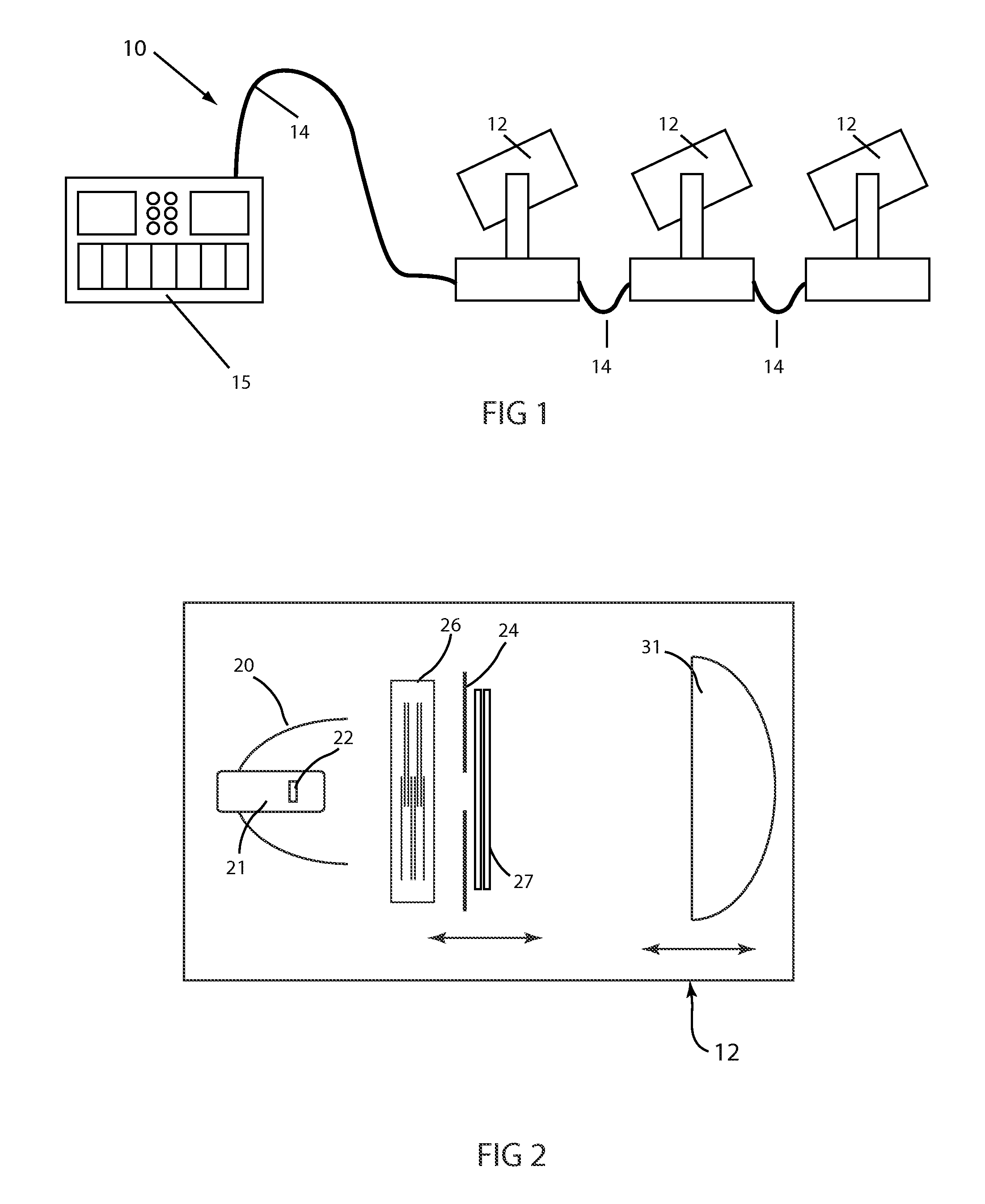
[0012]The present invention generally relates to an automated luminaire, specifically to the configuration of a variable image diffusion system within such a luminaire such that said image diffusion system provides a wide range and fine control of the applied image diffusion.

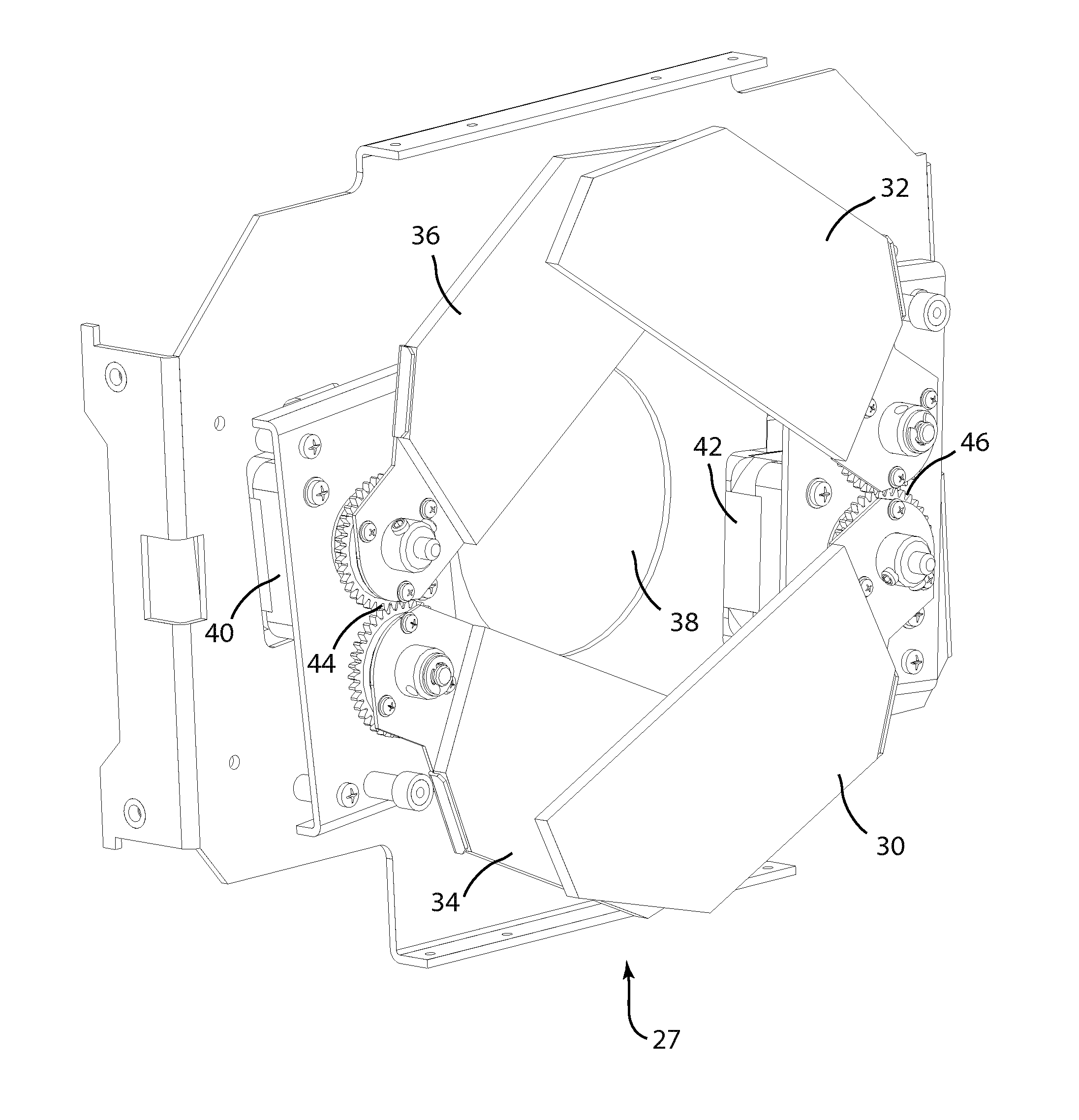
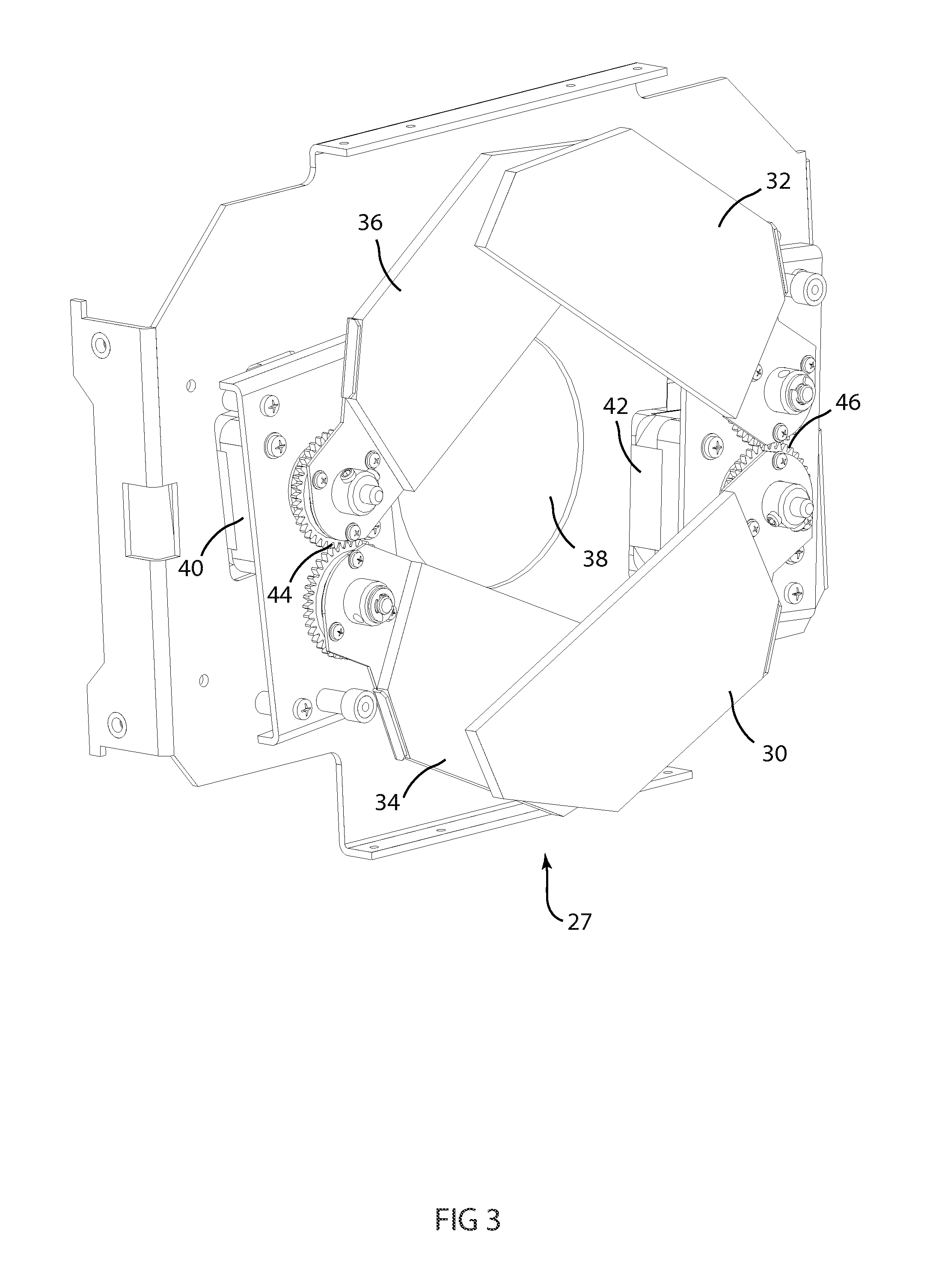
[0013]FIG. 3 illustrates an embodiment of the invention. Variable diffusion system 27 comprises two pairs of optical diffusion flags 30&32 and 34 and 36. First pair of optical diffusion flags 30 and 32 may be opened and closed over aperture 38 through gears 46 and motor 42. As motor 42 rotates, gears 46 are caused to rotate in contrary directions thus moving attached diffusion flags 30 and 32 in contrary directions. Second pair of optical diffusion flags 34 and 36 may be opened and closed over aperture 38 through gears 44 and motor 40. As m...


PUM


Abstract

Described are an improved automated luminaire 12 and luminaire systems 10 employing an improved image diffusion system 27. The image diffusion system 27 is improved by providing a plurality of sets of optical diffusion elements that may be operated either concurrently or consecutively so as to provide an improved range and control of the applied image diffusion

Description

TECHNICAL FIELD OF THE INVENTION[0001]The present invention generally relates to an automated luminaire, specifically to an optical system for use within an automated luminaire.BACKGROUND OF THE INVENTION[0002]Luminaires with automated and remotely controllable functionality are well known in the entertainment and architectural lighting markets. Such products are commonly used in theatres, television studios, concerts, theme parks, night clubs and other venues. A typical product will commonly provide control over the pan and tilt functions of the luminaire allowing the operator to control the direction the luminaire is pointing and thus the position of the light beam on the stage or in the studio. Typically this position control is done via control of the luminaire's position in two orthogonal rotational axes usually referred to as pan and tilt. Many products provide control over other parameters such as the intensity, color, focus, beam size, beam shape and beam pattern. The beam p...

Claims


Application Information

Patent Timeline
IPC IPC(8): F21V11/00
CPCF21W2131/406F21V11/18
Inventor JURIK, PAVEL
Owner ROBE LIGHTING
Why Eureka
Try Eureka