Pistol concealment device

a pistol and concealment device technology, applied in the field of pistol concealment devices, can solve the problems of limiting the access to safeties, magazines, magazine releases, and no adequate solution, and achieve the effect of stabilizing the pistol in the pock

Inactive Publication Date: 2011-05-12
TUZ MICHAEL
View PDF7 Cites 19 Cited by
  • Summary
  • Abstract
  • Description
  • Claims
  • Application Information

AI Technical Summary

Problems solved by technology

Various articles have been developed to address these issues, but none have provided an adequate solution.
U.S. Pat. No. 4,466,537 for “Concealable Holster,” describes a holster similar to the holster of the '523 patent, but is larger and somewhat cumbersome, in addition to having the same disadvantages as the '523 patent.
Such pouches further restrict access to safeties, magazines, magazine releases, etc., and are not suitable for pistols.
Further, pocket pistols are not well suited for aiming with standard sights.
An ideal solution is the addition of a laser site such as taught in U.S. Pat. No. 5,581,898 for “Modular Sighting Laser for a Firearm.” Unfortunately, the laser sight described in the '898 patent does not substantially alter the profile of a pistol carried in a pocket, and it interferes with the use of another device used to provide concealment.

Method used


Image

  • Pistol concealment device
  • Pistol concealment device
  • Pistol concealment device

Examples


Embodiment Construction

[0033]The following description is of the best mode presently contemplated for carrying out the invention. This description is not to be taken in a limiting sense, but is made merely for the purpose of describing one or more preferred embodiments of the invention. The scope of the invention should be determined with reference to the claims.

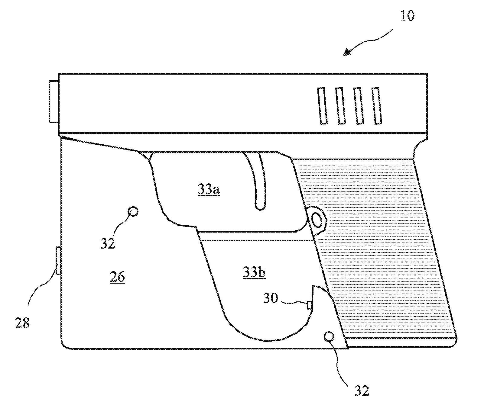
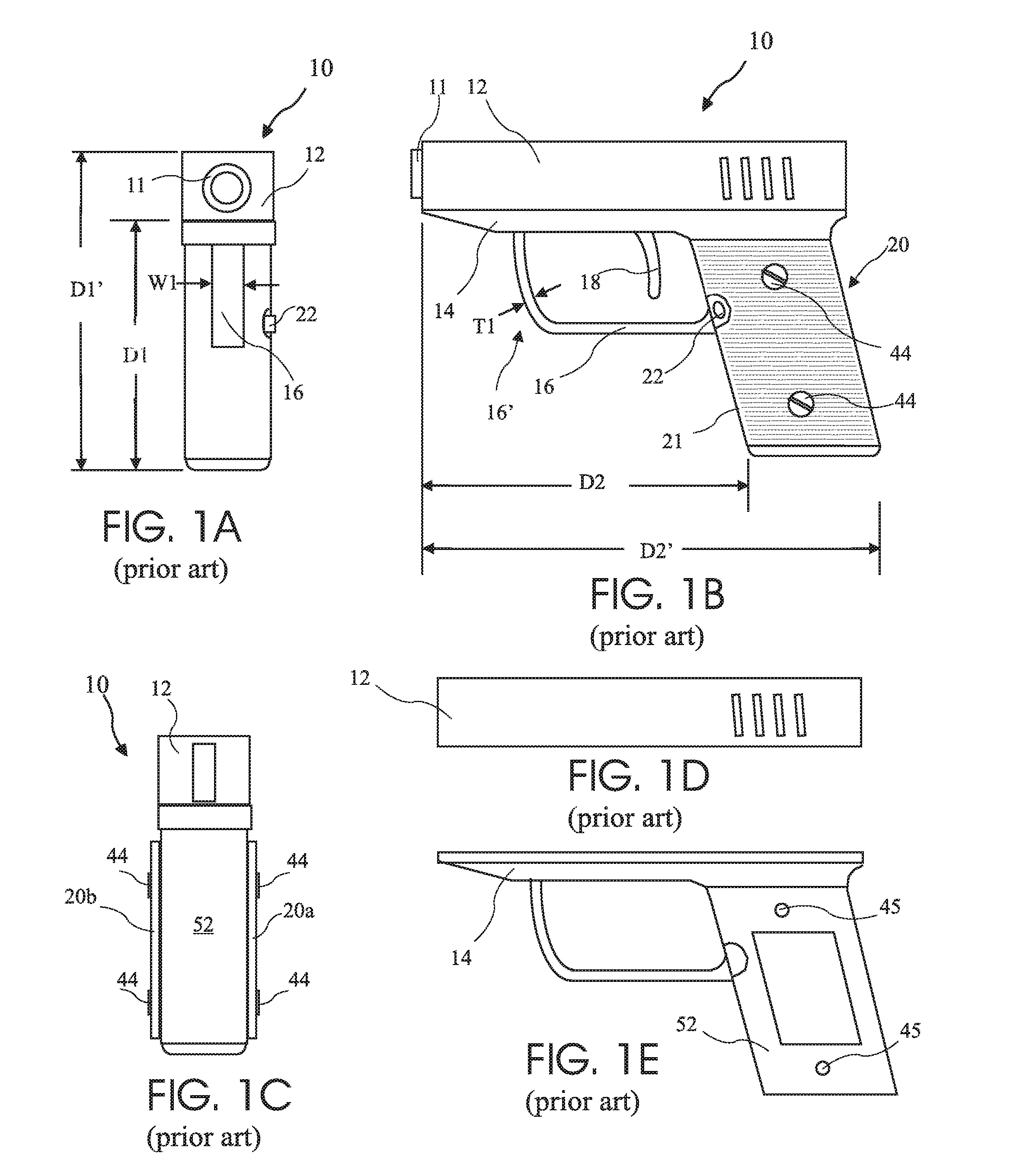
[0034]A typical prior art pistol 10 is shown in FIG. 1A in front view, and in FIG. 1B is side view. The pistol 10 includes a frame 14, barrel assembly comprising a barrel 11 and a slide 12, a grip 20, a trigger guard 16, a trigger 18, and a magazine release 22. The pistol 10 has a horizontal distance D2 between the grip 20 and the front of the pistol, and a distance D2′ which is the overall length of the pistol 10. The pistol 10 has a vertical distance D1 between the bottom of the barrel assembly and the bottom of grip portion 20, and a distance D1′ which is the overall height of the pistol 10. The trigger guard has a width W1 and a thickness T1. ...


PUM


Abstract

A pistol is concealed and stabilized by filling in an area below the barrel and in front of the grip with a spacer. The result is a rectangular shape similar to a wallet, which shape conceals the presence of the pistol when carried in a pocket (i.e., de-prints the pistol shape), and stabilizes the pistol in the pocket. The spacer may be attached to a trigger guard, to a portion of the pistol frame beneath the forward end of the barrel, or be integrated with the pistol grips, creating the rectangular shape. The spacer may further include a laser aiming device. In one embodiment, the spacer securely grasps a curved portion of the trigger guard and includes a contoured rear surface which is urged against a lower leading edge of the grip, thus firmly establishing a position for the device relative to the pistol.

Description

[0001]The present application is a Divisional of U.S. patent application Ser. No. 10 / 850,514 filed May 21, 2004 which claims the benefit of U.S. Provisional Application Ser. No. 60 / 546,694, filed Feb. 20, 2004, which applications are incorporated herein in their entirely by reference.BACKGROUND OF THE INVENTION[0002]The present invention relates to concealment of pocket pistols, and in particular to altering the profile of a pocket pistol to both alter the outline of a pistol carried in a pocket, and to stabilize the attitude of the pistol in the pocket.[0003]Off duty and plain clothes law enforcement officers generally carry concealed weapons, and are in some instances required to carry such weapons. When an officer carries a pocket pistol, the outline of the piston may be observable, and either alert a criminal, or create concern among bystanders. Various articles have been developed to address these issues, but none have provided an adequate solution.[0004]U.S. Pat. No. 4,387,523...

Claims


Application Information

Patent Timeline
Patent Type & Authority Applications(United States)
IPC IPC(8): F41C27/00F41G1/00
CPCF41C9/02F41G1/35F41C33/00F41C27/00
Inventor TUZ, MICHAEL
Owner TUZ MICHAEL
Why Eureka
Try Eureka