Protective cap for a stake

Inactive Publication Date: 2011-05-12
HOLMES JOSHUA B +1
View PDF10 Cites 0 Cited by
  • Summary
  • Abstract
  • Description
  • Claims
  • Application Information

AI Technical Summary

Benefits of technology

[0003]A protective cap is disclosed for use on the free end of stake projecting from the ground or other solid surface. The protective cap reduces the potential of impalement from an accidental fall onto such stakes. The protective cap includes a base platform, which is preferably a plate of about sixteen square inches. The base platform forms the top of the protective cap when the protective cap is placed on the stake.

Problems solved by technology

The protective cap reduces the potential of impalement from an accidental fall onto such stakes.

Method used


Image

  • Protective cap for a stake
  • Protective cap for a stake
  • Protective cap for a stake

Examples


Embodiment Construction

[0025]In the following description, reference is made to the accompanying drawings, which form a part hereof and which illustrate several embodiments of the present invention. The drawings and the preferred embodiments of the invention are presented with the understanding that the present invention is susceptible of embodiments in many different forms and, therefore, other embodiments may be utilized with structural changes that provide the same function in the same way and with the same result as described herein, without departing from the scope of the present invention.

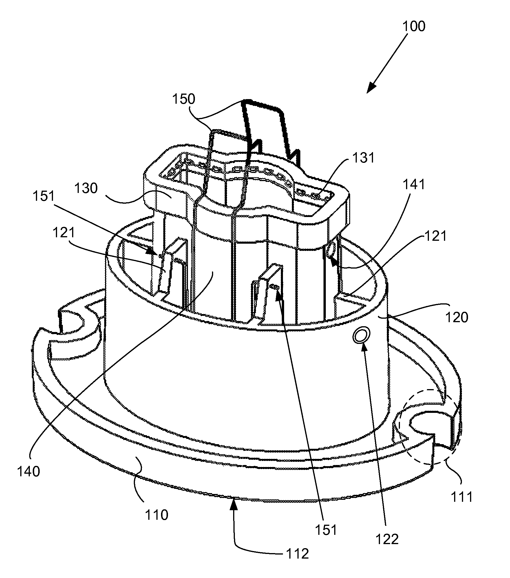
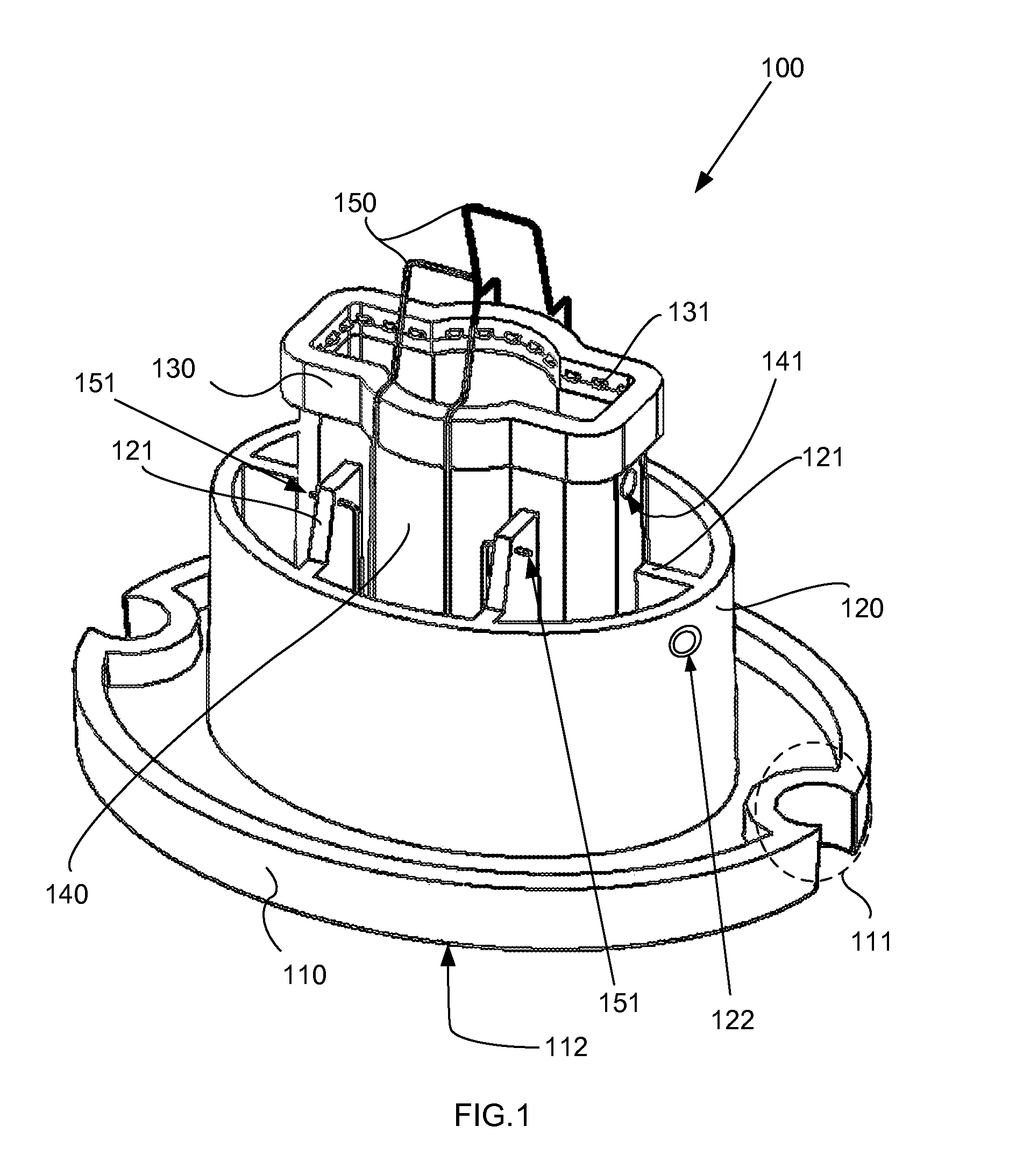
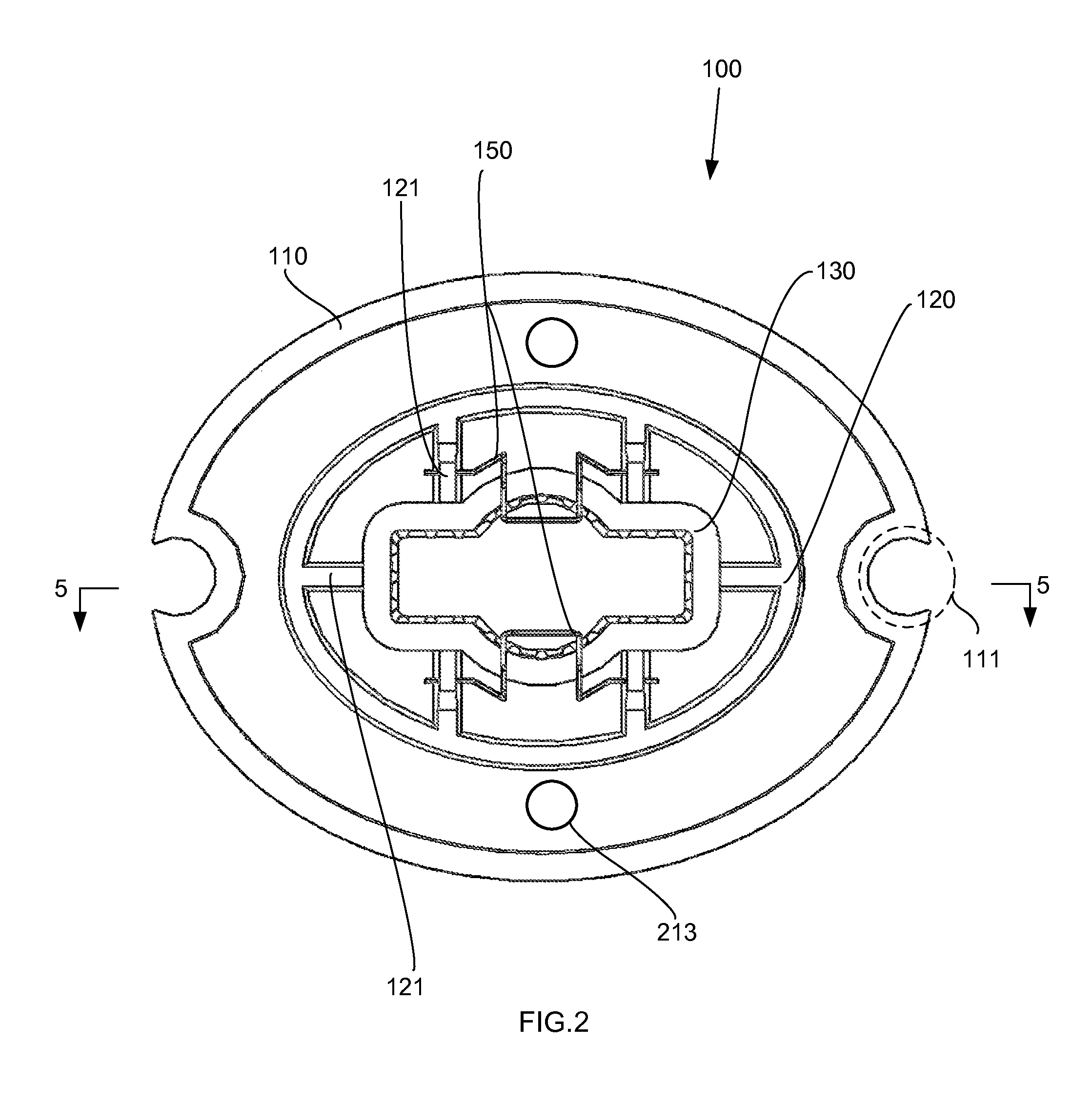
[0026]A preferred embodiment of the protective cap (100) is shown in perspective in FIG. 1, with other views of this embodiment in FIGS. 2 and 3. FIG. 4 shows is perspective of a tether (400) optionally used with the protective cap.

[0027]A protective cap (100) in accordance with the invention is for use on a free end of a stake projecting from a solid surface, such as the ground. The protective cap (100) may be use...


PUM


Abstract

A protective cap for use on the free end of a projecting stake includes a base platform, a receiving collar, a secondary collar, reinforcing ribs, and a cover. Optionally included are a plurality of metal clamps, and a tether. A horizontal hole in the receiving collar, or the secondary collar, provides a means for tethering the cap to the stake. Reinforcing ribs extend between the receiving collar and the secondary collar. Gripper teeth on the cover engage a variety of stake cross sections. An optional tether is configured with conical segments to engage with the horizontal holes. Optional notches and holes in the base platform would hold a glow stick.

Description

TECHNICAL FIELD[0001]In the field of static structures, a protective cap for mounting at the top of a shaft and so shaped as to be the final upper terminal of the structure.BACKGROUND ART[0002]Metal stakes are a common fixture in the construction industry. Depending on the style of the stake, caps or other protective attachments have been described. For example, U.S. Pat. No. 6,691,479 teaches a protective stake cap for placing atop a “T” shaped metal stake typically used in fencing applications. Innovativeness in this field, however, can greatly affect the protection offered by a cap against death or injury from an accidental human impact.SUMMARY OF INVENTION[0003]A protective cap is disclosed for use on the free end of stake projecting from the ground or other solid surface. The protective cap reduces the potential of impalement from an accidental fall onto such stakes. The protective cap includes a base platform, which is preferably a plate of about sixteen square inches. The bas...

Claims


Application Information

Patent Timeline
IPC IPC(8): B65D59/06
CPCE04H2017/006E04H15/62E04H17/006
Inventor HOLMES, JOSHUA B.ADKINS, CHET D.
Owner HOLMES JOSHUA B
Why Eureka
Try Eureka