Acoustic panel for an ejector nozzle

a technology of ejector nozzle and acoustic panel, which is applied in the field of acoustic panel, can solve the problems of not being able to produce acoustic parts, and local unsticking phenomena, so as to facilitate the mounting of acoustic structures and achieve good industrial feasibility

Active Publication Date: 2011-05-12
GERAKL +1
View PDF11 Cites 30 Cited by
  • Summary
  • Abstract
  • Description
  • Claims
  • Application Information

AI Technical Summary

Benefits of technology

This patent describes an acoustic panel that can be easily mounted between two skins and has no separate zones for sound insulation. It allows for the use of various materials while maintaining strong support structures. Overall, the technical effect of this design is improved installation flexibility and better performance under varying conditions.

Problems solved by technology

The technical problem addressed in this patent text is the need for a more cost-effective and lightweight material for the production of acoustic panels used in airplane propulsion assemblies to reduce noise. The current materials, such as titanium and super alloys, are expensive and have negative impacts on the mass of the aircraft.

Method used


Image

  • Acoustic panel for an ejector nozzle
  • Acoustic panel for an ejector nozzle
  • Acoustic panel for an ejector nozzle

Examples


Embodiment Construction

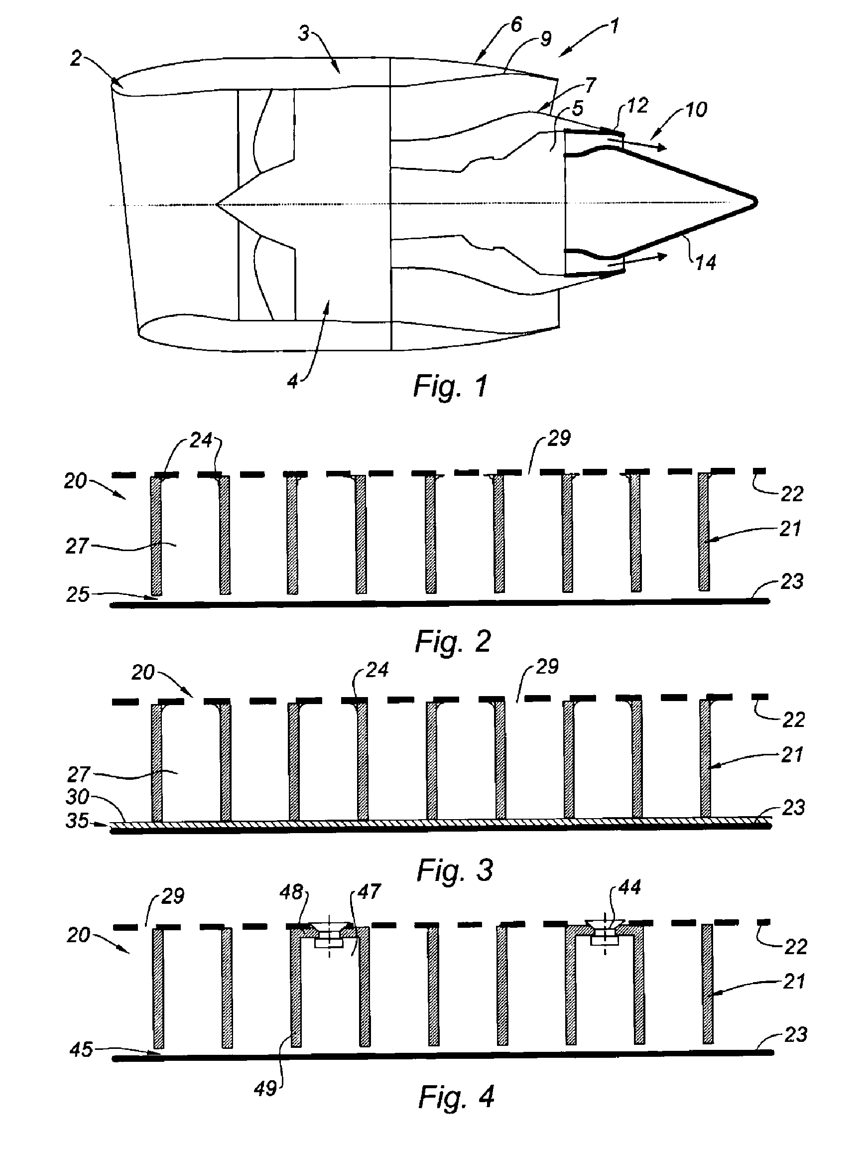
[0041]As shown in FIG. 1, a nacelle 1 according to the invention comprises an air intake lip 2, a middle structure 3 surrounding a fan 4 of a turbojet engine 5 and a downstream assembly 6. The downstream assembly 6 is formed by a inner fixed structure 7 (IFS) surrounding the upstream portion of the turbojet engine 5, an outer fixed structure (OFS) (not shown) and a moving cowl 9 including thrust reverser means. A suspension pylon (not shown) supports the turbojet engine 5 and the nacelle 1 of the invention.

[0042]The nacelle 1 of the invention ends with an ejection nozzle 10 comprising an external module 12 and an internal module 14. The internal 14 and external 12 modules define a flow channel for a primary so-called hot air stream exiting the turbojet engine 5.

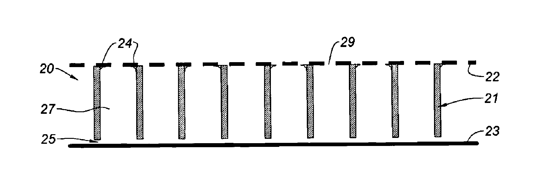
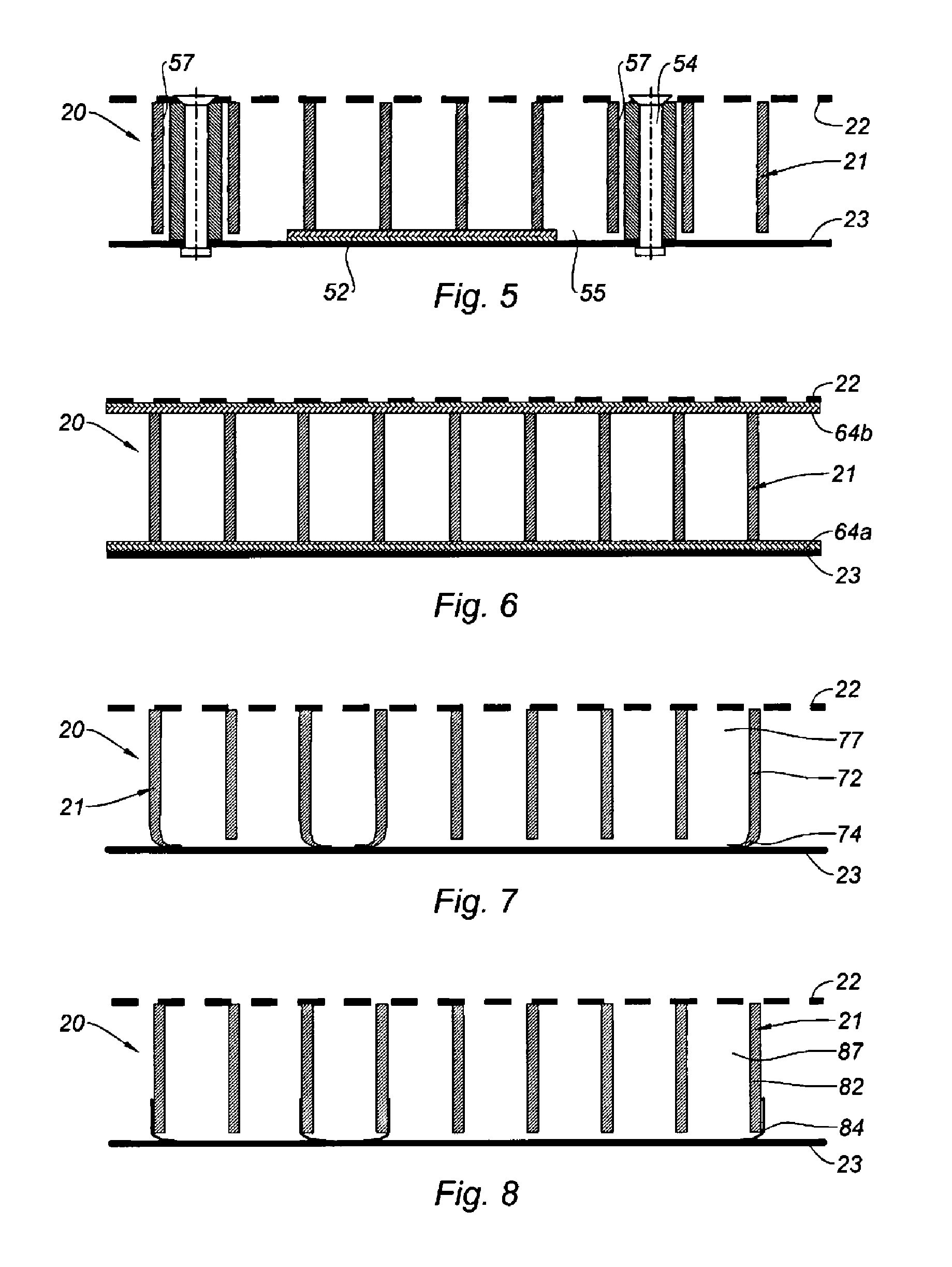
[0043]The internal 14 and external 12 modules comprise an acoustic panel comprising the following main components:[0044]an external skin containing acoustic holes,[0045]an internal skin,[0046]an acoustic structure comprising ...


PUM


Abstract

The invention relates to an acoustic panel (20) for an ejector nozzle (10) comprising the following main components: an external skin (22) containing acoustic holes (29); an internal skin (23); an acoustic structure (21) comprising alveolar-core cells (27) between the internal skin (23) and the external skin (22). At least one main component selected from the external skin (22), the internal skin (23) and the acoustic structure (21) is formed by a composite material and the acoustic structure (21) is held in contact with either or both of the internal (23) and external (22) skins by compression by elastic means and/or by fixing by mechanical fixing means (24). The invention also relates to an injector nozzle (10) and a nacelle (1) comprising such an acoustic panel (20).

Description


Claims


Application Information

Patent Timeline
Owner GERAKL
Why Eureka
Try Eureka