Liquid ejecting apparatus

Active Publication Date: 2011-05-12
SEIKO EPSON CORP
View PDF11 Cites 0 Cited by
  • Summary
  • Abstract
  • Description
  • Claims
  • Application Information

AI Technical Summary

Benefits of technology

[0020]An advantage of some aspects of the invention is that adhesion of paper dust, dust particles or the like (hereinafter referred to as “paper dust”) to the ink jet recording head is prevented with certainty without compromising the quality of recording.

Problems solved by technology

If an electric field in a certain direction is applied across the recording unit components, in an attempt to prevent paper dust from flying toward the ink jet recording head, paper dust will be charged to the opposite polarity, resulting in failure to prevent them from flying toward the ink jet recording head.
However, with such a configuration, the device would be larger in size and of higher cost due to complexity of the configuration.
In addition, the air blown from the air duct may undesirably cause paper dust to adhere to the recording head.
However, this technique has some problems in that the paper dust collecting member does not always effectively collect paper dust due to the above mentioned opposite polarity, and paper dust accumulated on the paper dust collecting member needs to be disposed of (removed).
In particular, when a significant amount of paper dust is accumulated, a slight vibration or impact may cause paper dust to be released into the air, which makes it difficult to maintain the performance over a long period of time.

Method used


Image

  • Liquid ejecting apparatus
  • Liquid ejecting apparatus
  • Liquid ejecting apparatus

Examples


Embodiment Construction

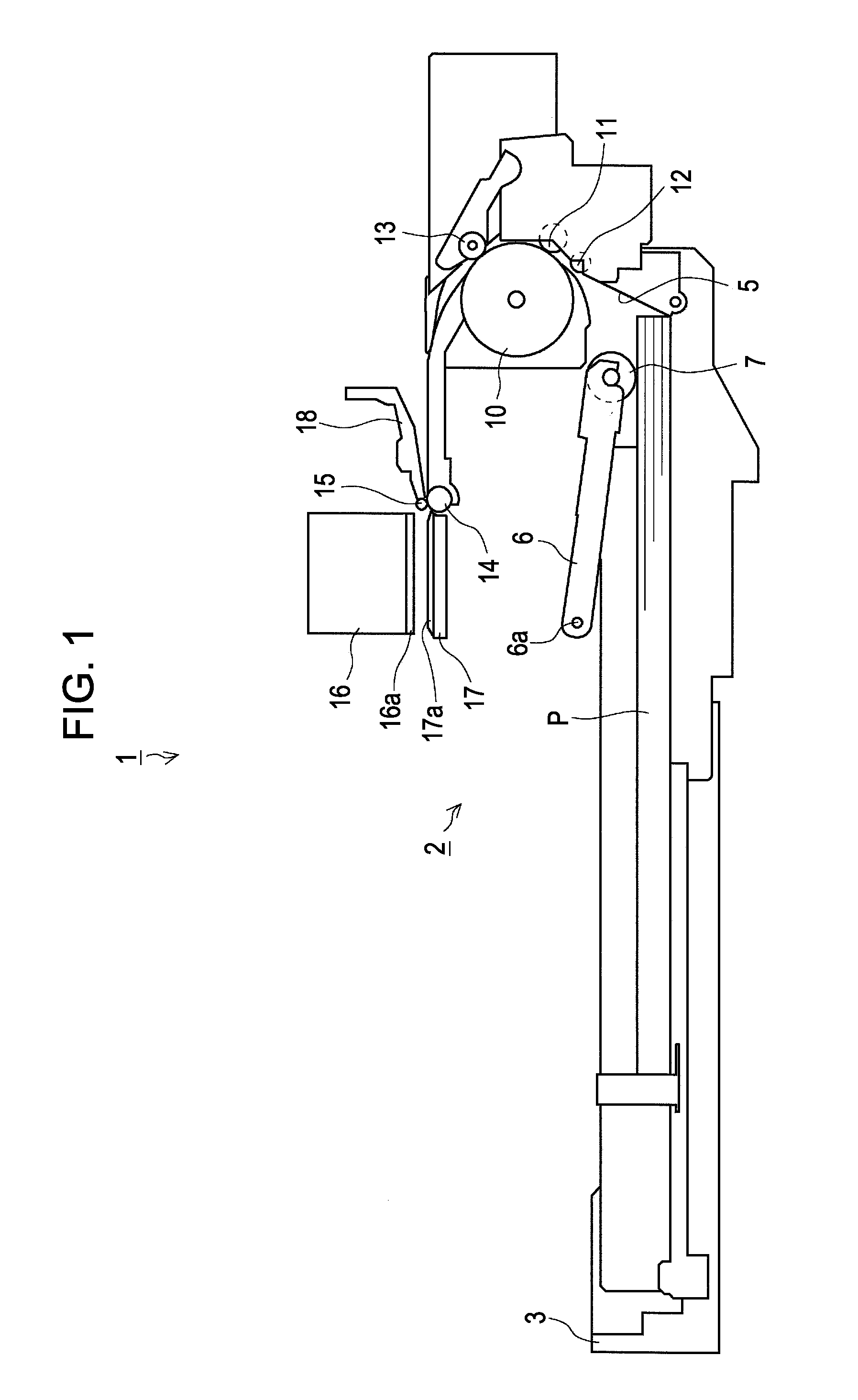
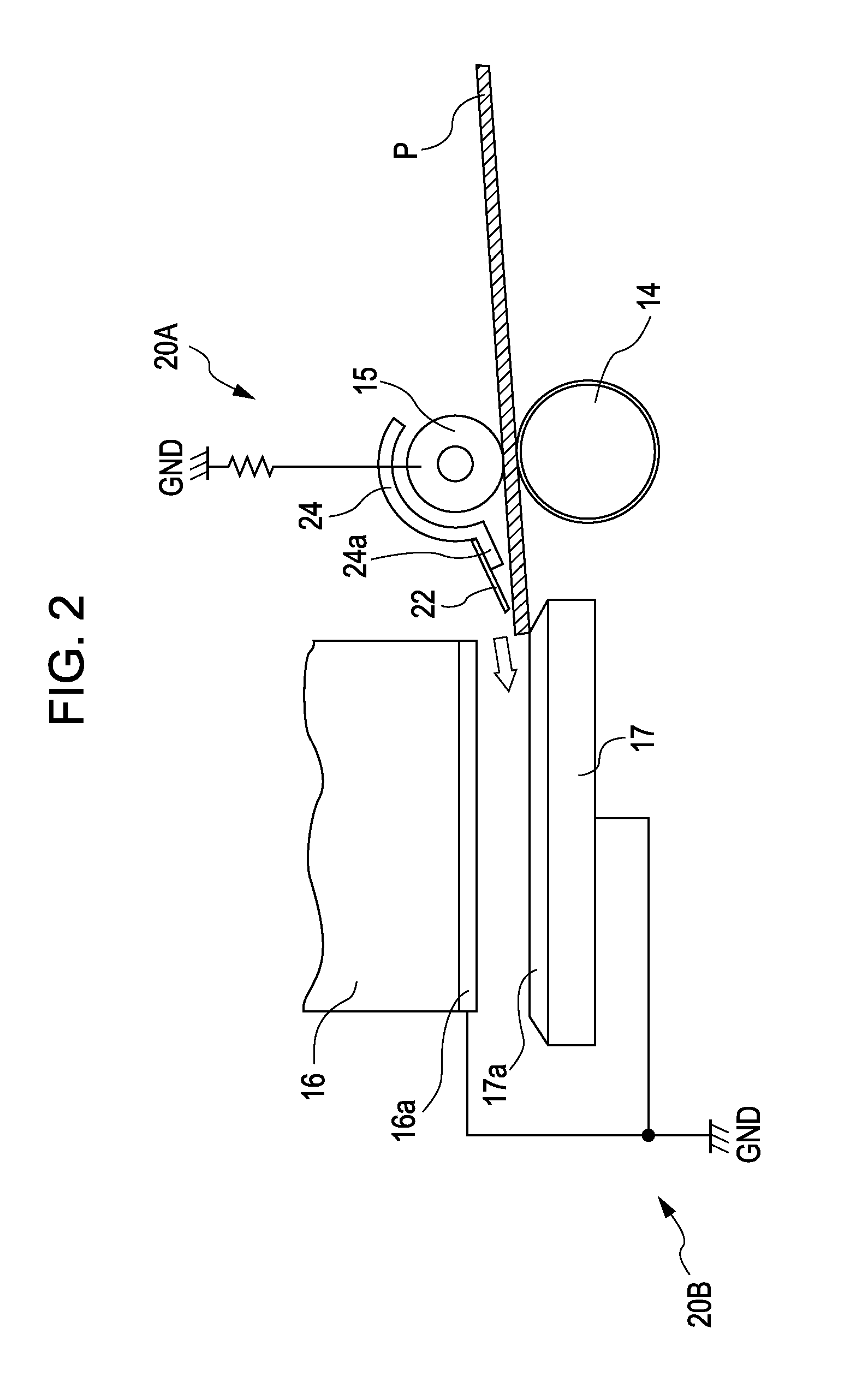
[0041]Embodiments of the invention will be described below with reference to the accompanying drawings. FIG. 1 shows a schematic sectional side view of a sheet transportation path of an ink jet printer 1 in accordance with the invention. FIGS. 2 and 3 show a side view and a plan view of a recording execution section in the ink jet printer 1, respectively.

[0042]Referring to FIG. 1, an overall configuration of the ink jet printer 1 which is common to the respective embodiments will be briefly described. The ink jet printer 1 includes a sheet feeder 2 in the bottom portion of the apparatus and is configured such that a recording sheet P, as an example of a target ejection medium, is fed out of the sheet feeder 2 via an intermediate roller 10, around which the recording sheet P is turned and reversed, to an ink jet recording head 16 as a liquid ejecting unit to perform recording.

[0043]More specifically, the sheet feeder 2 includes a sheet cassette 3, a pickup roller 7, the intermediate ...


PUM


Abstract

A liquid ejecting apparatus having a liquid ejecting unit that ejects liquid toward a target ejection medium and a target ejection medium support member that is disposed so as to oppose the liquid ejecting unit and supports the target ejection medium, includes a conductive shielding member that covers a first side of the target ejection medium, which opposes the liquid ejecting unit, at an edge area including an edge perpendicular to a feeding direction of the target ejection medium.

Description

BACKGROUND[0001]1. Technical Field[0002]The present invention relates to liquid ejecting apparatuses such as facsimile machines and printers.[0003]2. Related Art[0004]As an example of liquid ejecting apparatuses, an exemplary ink jet printer will be described below. An ink jet printer is provided with an inkjet recording head and a support member (also referred to as a platen) which is arranged so as to oppose the ink jet recording head. The ink jet printer is configured such that when a recording sheet is supported by the support member, a distance is defined between the ink jet recording head and the recording sheet.[0005]In recent years, development of ink jet printers has been carried out with the aim of further improving the quality of recording by minimizing the size of each ink droplet, which is minimized to for example several picoliters. As a result, when those ink droplets are ejected from the ink jet recording head toward the recording sheet, some of them may not land on ...

Claims


Application Information

Patent Timeline
IPC IPC(8): B41J2/01
CPCB41J11/06B41J11/0065
Inventor YAMADA, YOICHIKATSUKI, KIYOTERUKOBASHI, MASARUMATSUMOTO, DAISUKEKOIKE, YASUNORI
Owner SEIKO EPSON CORP
Why Eureka
Try Eureka