Method for determining discrete fracture networks from passive seismic signals and its application to subsurface reservoir simulation

a discrete fracture network and seismic signal technology, applied in seismicology, instruments, measurement devices, etc., can solve the problems of few measurements that can provide fracture size in a particular reservoir, and the above methods have proved less than satisfactory for use with reservoir simulation

Inactive Publication Date: 2011-05-12
MICROSEISMIC
View PDF17 Cites 56 Cited by
  • Summary
  • Abstract
  • Description
  • Claims
  • Application Information

AI Technical Summary

Benefits of technology

[0015]A method for mapping a fracture network from microseismic signals according to one aspect of the invention include determining a source of at least one seismic event from features in the signals exceeding a selected amplitude (“visible seismic event”). The signals are generated by recording output of a plurality of seismic receivers disposed proximate a volume of the Earth's subsurface to be evaluated. The signals are electrical or optical and represent seismic amplitude. A source mechanism of the at least one visible seismic event is determined. A fractu

Problems solved by technology

In general, there are very few measurements that can provide fracture size in a particular reservoir away

Method used


Image

  • Method for determining discrete fracture networks from passive seismic signals and its application to subsurface reservoir simulation
  • Method for determining discrete fracture networks from passive seismic signals and its application to subsurface reservoir simulation
  • Method for determining discrete fracture networks from passive seismic signals and its application to subsurface reservoir simulation

Examples


Embodiment Construction

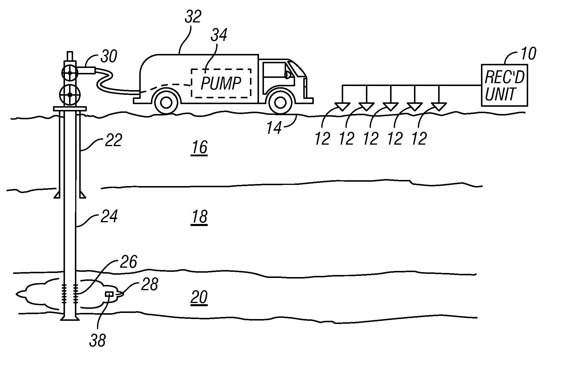
[0023]FIG. 1 shows a typical arrangement of seismic receivers as they would be used in one application of a method according to the invention. The embodiment illustrated in FIG. 1 is associated with an application for passive seismic emission tomography known as “fracture monitoring.” It should be clearly understood that the application illustrated in FIG. 1 is only one possible application of a method according to the invention. In other applications, passive seismic monitoring may take place in the absence of equipment shown in FIG. 1 used for pumping fluids into the subsurface formations.

[0024]In FIG. 1, each of a plurality of seismic receivers, shown generally at 12, is deployed at a selected position proximate the Earth's surface 14, generally above or proximate to a volume of the subsurface to be evaluated. The seismic receivers 12 can also be deployed in one or more wellbores (not shown) drilled through the subsurface. In marine applications, the seismic receivers would typic...


PUM


Abstract

A method for mapping a fracture network that includes determining a source of at least one seismic event from features in recorded seismic signals exceeding a selected amplitude (“visible seismic event”). The signals are generated by a plurality of seismic receivers disposed proximate a volume of subsurface to be evaluated. The signals are electrical or optical and represent seismic amplitude. A source mechanism of the at least one visible seismic event is determined. A fracture size and orientation are determined from the source mechanism. Seismic events are determined from the signals from features less than the selected amplitude (“invisible seismic events”) using a stacking procedure. A source mechanism for the invisible seismic events is determined by matched filtering. At least one fracture is defined from the invisible seismic events. A fracture network model is generated by combining the fracture determined from the visible seismic event with the fracture determined from the invisible seismic events.

Description

CROSS-REFERENCE TO RELATED APPLICATIONS[0001]Not applicable.STATEMENT REGARDING FEDERALLY SPONSORED RESEARCH OR DEVELOPMENT[0002]Not applicable.BACKGROUND OF THE INVENTION[0003]1. Field of the Invention[0004]The invention relates generally to the field of determining subsurface structures from passive seismic signals. More specifically, the invention relates to methods for determining networks of rock formation fractures using passive seismic signals. The fracture network may be used as input to simulations of fluid flow through subsurface reservoirs.[0005]2. Background Art[0006]Reservoir simulation is a process by which fluid flow from one or more permeable subsurface rock formations is estimated with respect to time. Such estimation is important for, for example, in determining the economic value of a subsurface hydrocarbon reservoir. The estimation is also useful in determining most profitable places to drill wellbores through such reservoirs, production rates of existing wells a...

Claims


Application Information

Patent Timeline
IPC IPC(8): G01V1/28
CPCG01V2210/123G01V1/288
Inventor WILLIAMS-STROUD, SHERILYNEISNER, LEO
Owner MICROSEISMIC
Why Eureka
Try Eureka