Actuated self unplugging surgical sucker wand

a self-unplugging, sucker technology, applied in the direction of suction devices, intravenous devices, other medical devices, etc., can solve the problems of affecting the suction effect, etc., to achieve the effect of high blast of co2

Inactive Publication Date: 2011-05-12
STIEHL TECH
View PDF39 Cites 10 Cited by
  • Summary
  • Abstract
  • Description
  • Claims
  • Application Information

AI Technical Summary

Benefits of technology

In another aspect, the invention is directed to a suction wand for use in aspirating a surgical site during an orthopedic surgical operation which yields bone debris and generally comprises a handle and a suction conduit at least partially disposed in the handle and partially defining a suction path. A suction tip is at an end of the suction conduit. The suction path is adapted to communicate with a vacuum source at a vacuum source end of the suction path remote from the suction tip such that the suction path extends from the suction tip through the suction conduit to the vacuum source. A CO2 gas conduit is adapted for fluid communication with a gas source and is at least partially disposed in the handle and partially defines a CO2 path. A CO2 gas conduit valve is operable between an open position in which CO2 gas flows from the gas source through the CO2 conduit and out the suction tip and a closed position in which CO2 gas does not flow out of the suction tip. A filter screen is disposed in the suction path for retaining bone debris produced during the operation. The filter screen comprises a wire mesh including a set of parallel horizontal wires and a set of parallel vertical wires woven with the horizontal wires forming gaps between the wires. The gaps are sized and arranged to retain the bone debris on the screen when the wand is in a suction mode and permit a high blast of CO2 to impinge upon the retained debris when the wand is in a CO2 pressure mode to expel the debris from the screen.

Problems solved by technology

The apparatus disclosed in Prusmack is not ideal because the tissue and clot can travel through device all the way to the valve mechanisms, potentially damaging the device.
The irrigation function is complicated as it requires both turning of a stopcock and operation of a button to move the irrigation channel into the main flow path.
Also, it does not inhibit larger potentially clogging debris from being sucked into the device beyond the point where the declogging function can be effective.
As shown in the Prusmack publication, a major obstacle to the optimal performance of sucker wands is the obstruction that occurs when bone bits and other debris are sucked into the suction line, effectively clogging the egress of fluids away from the surgical site and blocking the suction.
A secondary problem has been the relatively high flow of air through the wand during the surgical procedure which leads to the potential deposition of airborne bacteria on the tip of the wand.
And because the wand tip is moistened by the egress of fluid during suction, the wand tends to attract dust or debris which are then expelled to the surgical site when positive pressure is produced.

Method used


Image

  • Actuated self unplugging surgical sucker wand
  • Actuated self unplugging surgical sucker wand
  • Actuated self unplugging surgical sucker wand

Examples


second embodiment

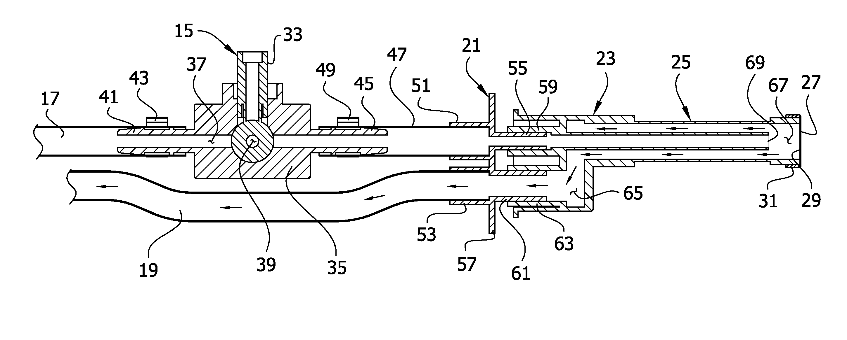
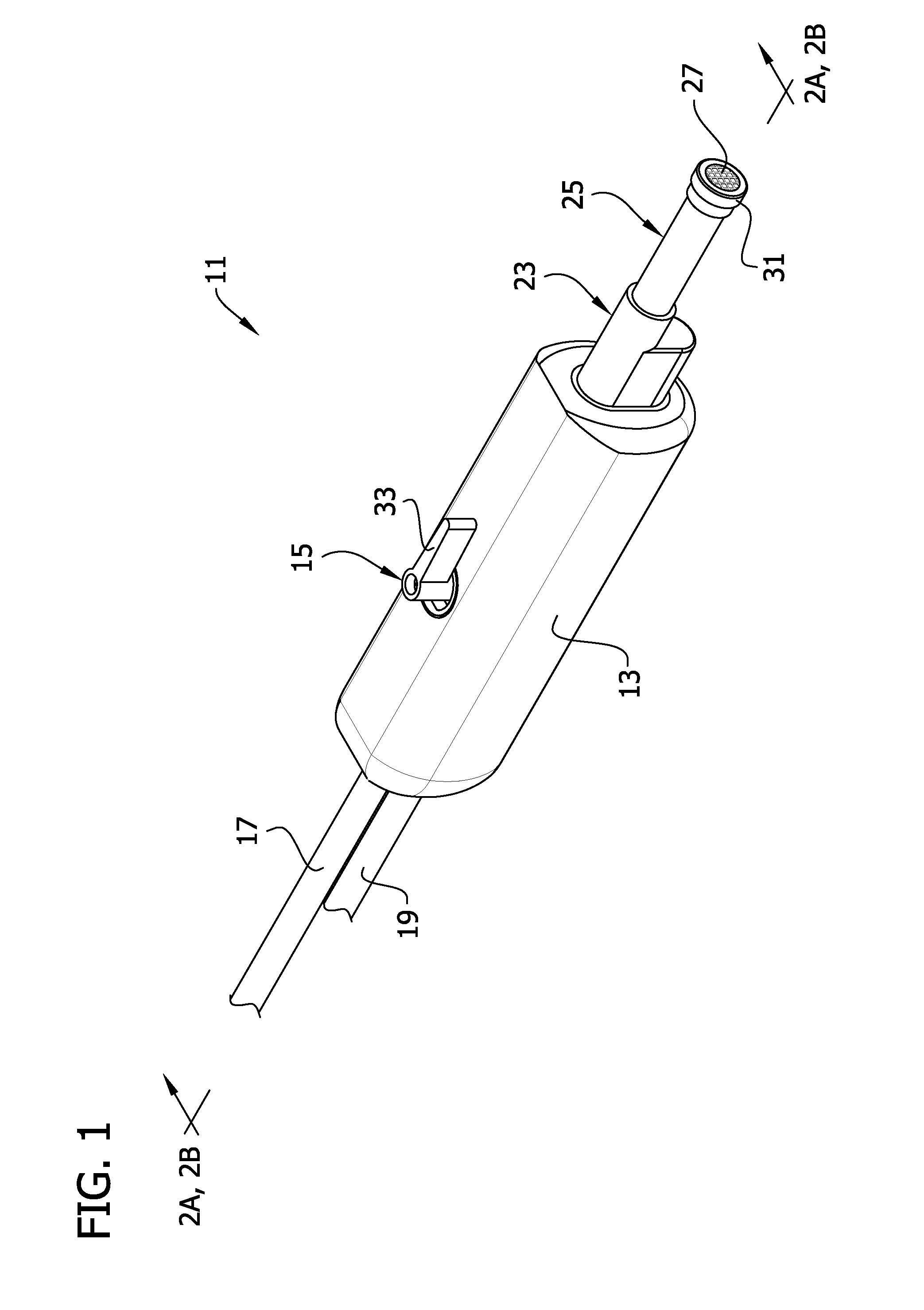
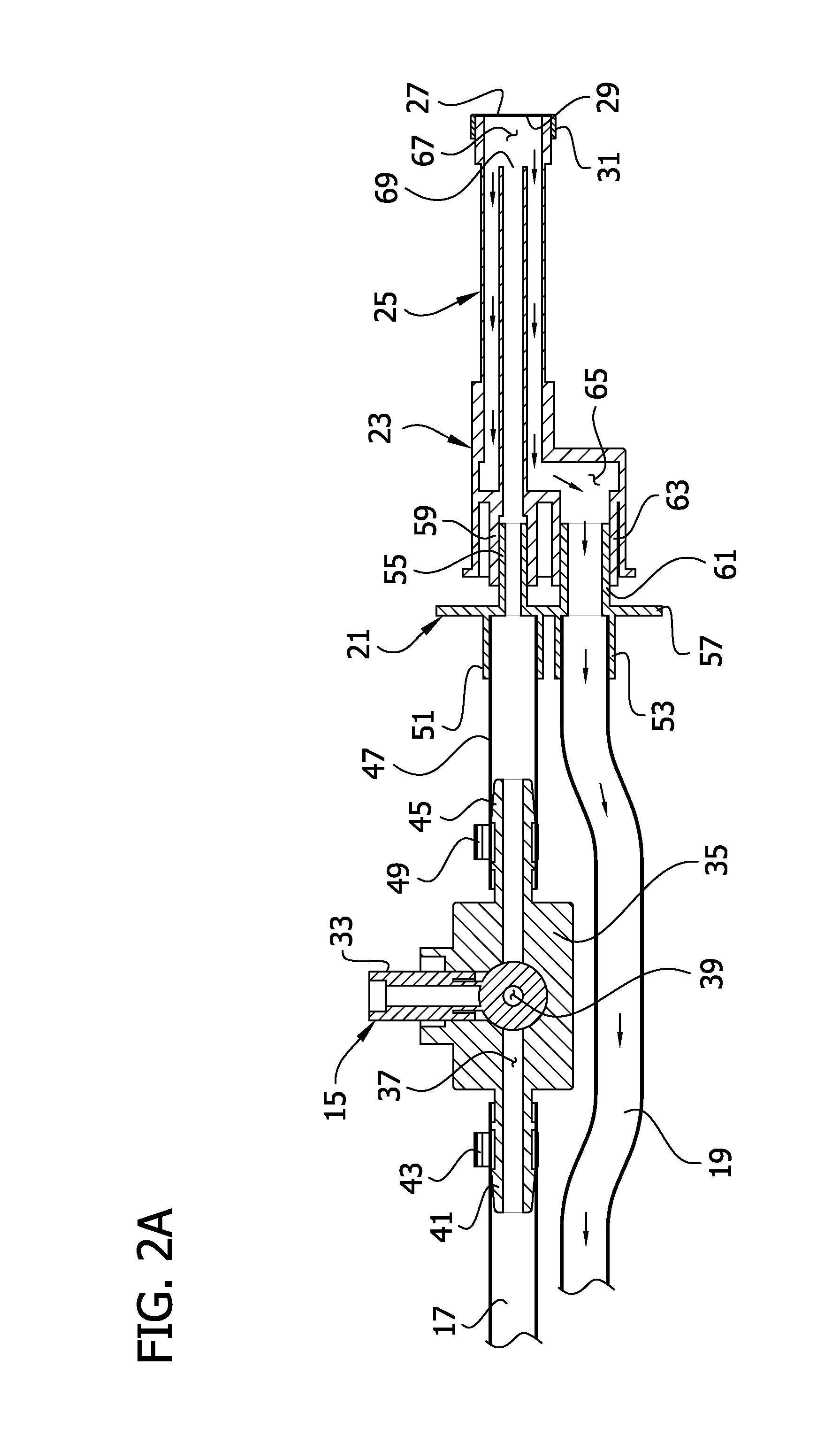
a suction wand 111 of the present invention is shown in FIG. 5. The wand 111 of the second embodiment comprises a handle 113 and a valve 115 partially received in the handle moveable between an open and closed position. In the illustrated embodiment, the valve 115 is a ball valve. In the open position, an inflow tube 117 can deliver positive pressure from a positive pressure source (not shown) to a positive pressure conduit 121 in the handle 113. The positive pressure conduit 121 extends through the handle 113 out a distal end of the handle to a tip portion 125. A filter screen 127 is disposed in an open, distal end of the tip portion 125. The wand 111 is configured to deliver a positive pressure force at the tip portion 125 of about 50 psi.

An outflow tube 119 extends through the handle 113 and connects to a suction conduit 123 in the handle. The suction conduit 123 also extends through the handle 123 and out the distal end of the handle to the tip portion 125. The positive pressure...

third embodiment

a suction wand 211 of the present invention is shown in FIG. 6. The third embodiment is substantially the same as the second embodiment except for valve 215 which is configured to control the delivery of pressure in both the suction conduit 223 and the positive pressure conduit 221. The valve 215 is configured such that in a first position the valve closes the positive pressure conduit 221 and opens the suction conduit 223. In a second position, the valve 215 closes the suction conduit 223 and opens the positive pressure conduit 221. In the illustrated embodiment, the valve 215 is a double-ball valve. However, other suitable valves can be used within the scope of the invention.

fourth embodiment

a suction wand 311 of the present invention is shown in FIG. 7. The wand 311 of the fourth embodiment comprises an inflow tube 317 and an outflow tube 319 adapted for connection to respective positive pressure and negative pressure sources. The tubes 317, 319 are connected to a switch 315 at their distal ends. A hose 323 extends from the switch and connects to a positive pressure / suction conduit 321 received in a handle 313 of the wand 311. A button 232 on the handle 313 is depressable to move the switch 315 between the inflow and outflow tubes 317, 319 to selectively communicate one of the tubes with the hose 232. A tip portion 325 extends from a distal end of the handle 313 and has a filter screen 327 disposed in an open distal end. This embodiment is similarly configured to generate a positive pressure force of about 50 psi at the open distal end of the tip portion 325.

Having described the invention in detail, it will be apparent that modifications and variations are possible wit...


PUM


Abstract

A suction wand for use during a surgical operation involving cutting of bone which yields bone debris, the wand comprising a suction conduit, a suction tip, a filter screen for retaining bone debris, and a carbon dioxide gas conduit for directing gas toward the suction tip to expel debris from the filter screen.

Description

CROSS-REFERENCE TO RELATED APPLICATIONSThis application is a non-provisional application of U.S. Ser. No. 61 / 259,111, filed Nov. 6, 2009, the entirety of which is incorporated herein by reference.FIELD OF THE INVENTIONThe present invention generally relates to a suction device for use in surgical procedures and more particularly to a surgical suction device for removing debris from a surgery site.BACKGROUND OF THE INVENTIONSuction devices are commonly used in a variety of medical applications to evacuate various fluids from a patient for a variety of purposes. For example, during surgery, blood and other body fluids are commonly removed to permit visual inspection of the surgical site and disposal of fluids. Suction wands may also provide for the production of positive pressure (usually air or water) to irrigate the surgical site. One such example is disclosed in Lester, U.S. Pat. No. 4,526,573 which shows a suction conduit from sucking debris away from the surgery site and an irrig...

Claims


Application Information

Patent Timeline
Patent Type & Authority Applications(United States)
IPC IPC(8): A61M1/00
CPCA61M1/0041A61M2205/7554A61M1/0084A61M1/0064A61M1/741A61M1/774A61M1/85
Inventor STIEHL, JAMES B.STIEHL, KURT R.
Owner STIEHL TECH
Why Eureka
Try Eureka