Water supply system for a linearly moving sprinkler irrigation system

Inactive Publication Date: 2011-05-19
MARCY SAMUEL J
View PDF12 Cites 3 Cited by
  • Summary
  • Abstract
  • Description
  • Claims
  • Application Information

AI Technical Summary

Benefits of technology

[0013]The present invention provides apparatus and techniques to get supply water from a fixed location such as a well or hydrant to a moving linear irrigation system in an economical and convenient manner. Water from the fixed location is directed to a stationary water conveyance system, i.e. a closed conduit. The stationary water conveyance system has a traveling opening such that a pressurizing pickup shoe mounted on a moving linear irrigation system can extend down through the traveling opening in the stationary water conveyance system to take water from that system. The pressurizing pickup shoe comprises (1) an inlet for intercepting the water in the stationary water conveyance system (i.e. a conduit), (2) a seal (preferably around the periph

Problems solved by technology

Disadvantages of the center pivot system are adapting the circular pattern to square or rectangular fields and the fact that each nozzle travels at a rate proportional to its distance from the pivot point and must therefore be individually calibrated such that the rate of water application is as uniform as possible over the entire field.
Linear systems alleviate the two listed disadvantages of the center pivot system because their spraying patterns are rectangular and each nozzle sprays at the same rate, but they create another problem of their own.
This problem is getting the supply water into the moving linear irrigation system.
Because of this problem and the high cost of overcoming it with existing technology, linear systems are not now as widely used as are center pivot systems.
For the great majority of fields, this is not feasible, so that the hose drag method is now the most prevalent method of getting supply water into a moving linear ir

Method used


Image

  • Water supply system for a linearly moving sprinkler irrigation system
  • Water supply system for a linearly moving sprinkler irrigation system
  • Water supply system for a linearly moving sprinkler irrigation system

Examples


Embodiment Construction

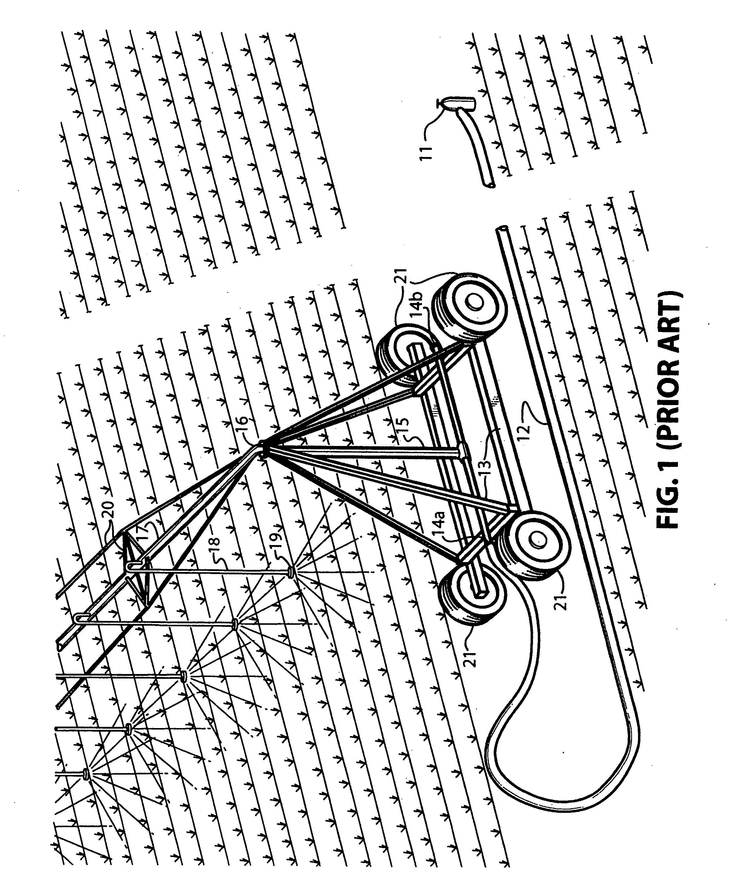
[0035]FIG. 1 shows a prior art technique and system for getting water into a linear irrigation system and sprayed onto crops. Water from hydrant 11 enters hose 12, which is connected to cart 13 at either point 14a or 14b. The water then flows up vertical feed pipe 15 to a swivel connection 16, thence out into a main water line 17. The water then flows down through drops 18 to nozzles 19 where it is sprayed onto the crops. Swivel connection 16 enables the main line to be rotated 180° so that crops on the opposite side of cart 13 can be irrigated. The main water line 17 is supported by truss structure 20. Cart 13 has drive wheels 21 which propel the cart 13 down the field, dragging one end of hose 12 along with it.

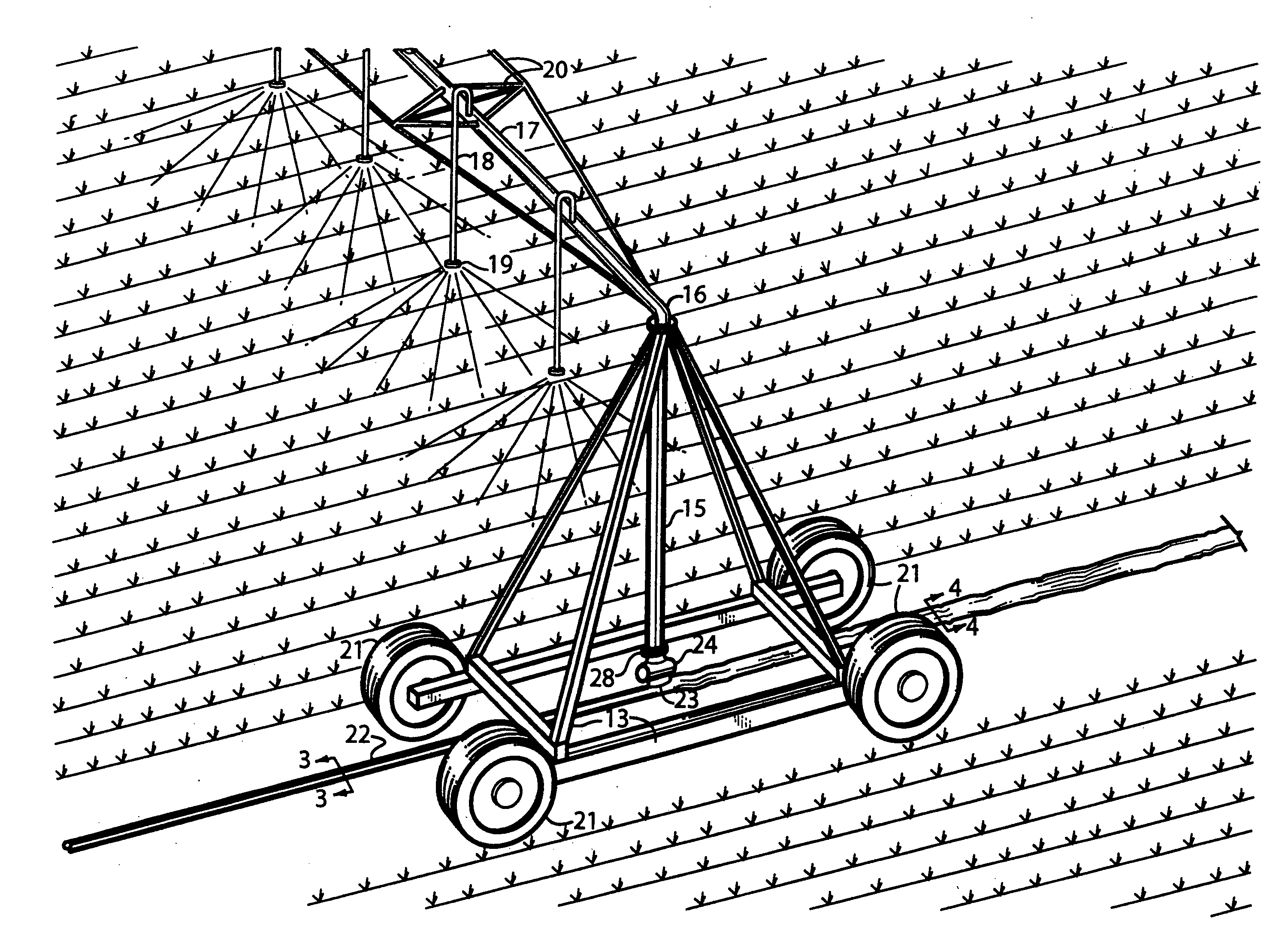
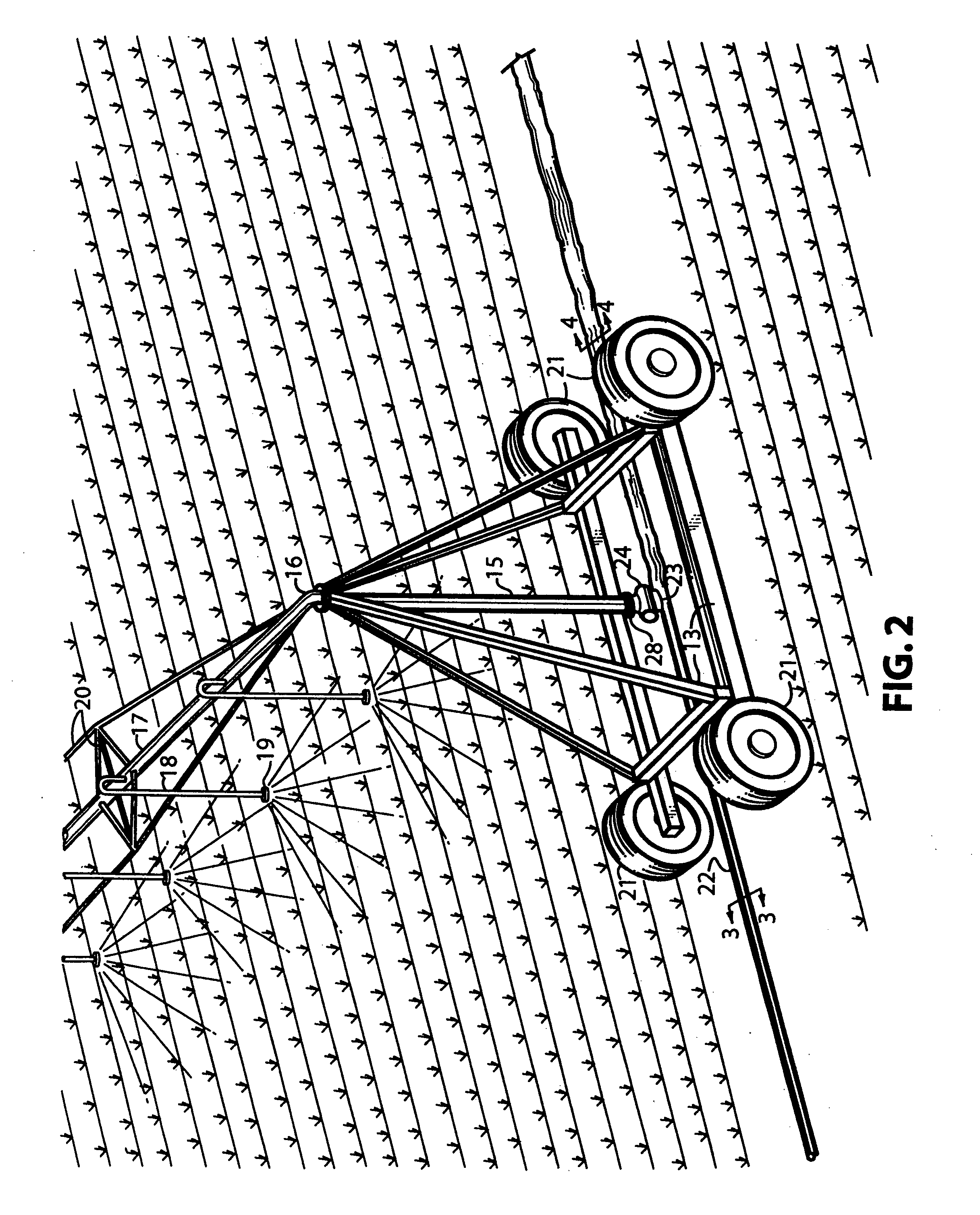
[0036]FIG. 2 illustrates how the present invention connects with the sprinkler apparatus of the type shown in FIG. 1. Water is directed into stationary closed conduit 22. Conduit 22 has a traveling opening 23 that moves together with cart 13 such that the traveling opening 2...


PUM


Abstract

A water supply system is described for supplying water to a linearly moving irrigation system. The water supply system is able to take water from a stationary water supply conduit (either a collapsible conduit or a rigid conduit) and feed it into one end of a feed pipe for the irrigation system. The water supply system includes a pickup shoe which extends into the water supply conduit through a traveling opening in the top side of the conduit. The pickup shoe intercepts substantially all of the water in the supply conduit and pumps it upwardly through the traveling opening to the feed pipe for the irrigation system. The pump is located in the portion of the shoe which extends into the supply conduit.

Description

CROSS-REFERENCE TO RELATED APPLICATION[0001]This application is a continuation-in-part of my copending application Ser. No. 11 / 445,705, filed Jun. 2, 2006, which is based upon, and claims priority from, my Provisional Application No. 60 / 688,117, filed Jun. 7, 2005.FIELD OF THE INVENTION[0002]This invention relates generally to field irrigation systems. More particularly, this invention relates to linearly moving sprinkler systems. Even more particularly, this invention relates to water supply systems for supplying water from a stationary conduit at a continuously changing location to a linearly moving sprinkler irrigation system.BACKGROUND OF THE PRIOR ART[0003]Efficient irrigation of large fields with sprinklers requires that a relatively small number of sprinkling nozzles be moved over the field. One method of accomplishing this is to mount these nozzles on an overhead moving pipeline. The most prominent system now in use is called a center pivot and consists of an overhead pipeli...

Claims


Application Information

Patent Timeline
IPC IPC(8): F16L3/00
CPCA01G25/097Y10T137/6851Y10T137/85978Y10T137/86268Y02A40/22
Inventor MARCY, SAMUEL J.
Owner MARCY SAMUEL J
Why Eureka
Try Eureka