Lighting device for vehicle

a technology for lighting devices and vehicles, applied in vehicle interior lighting, interior lighting purposes, transportation and packaging, etc., can solve the problems of insufficient illumination of the floor, the lamp is distant from the floor, and the floor cannot be illuminated with sufficient illuminance, so as to achieve smooth entry or exit of the vehicle

Inactive Publication Date: 2011-05-19
FALTEC CO LTD
View PDF4 Cites 9 Cited by
  • Summary
  • Abstract
  • Description
  • Claims
  • Application Information

AI Technical Summary

Benefits of technology

[0008]The present invention has been made to overcome the above-mentioned problems, and it is an object of the present invention to provide a lighting device for a vehicle that can sufficiently illuminate a floor in a cabin without illuminance reduction due to an object such as an instrument panel or a seat disposed between the lighting device and the floor, and can surely illuminate the floor around a user's feet when the user is getting in or off the vehicle.
[0010]According to the aspect of the present invention, the floor lamp is provided close to the floor in the cabin. Accordingly, the floor lamp can sufficiently illuminate the floor in the cabin without illuminance reduction due to an object such as an instrument panel or a seat disposed between the floor lamp and the floor.
[0012]According to this configuration, the floor lamp can efficiently illuminate the floor in the cabin without illuminance reduction due to an object such as an instrument panel or a seat disposed between the floor lamp and the floor.
[0015]According to this configuration, mounting of the floor lamp on the inner sill cover does not cause a height elevation of the inner sill cover. Accordingly, a user can smoothly get in or off the vehicle without being obstructed by the inner sill cover.
[0017]According to this configuration, the floor lamp does not largely project toward the cabin from the inner sill cover, and the lights can be irradiated widely. Accordingly, the floor lamp can illuminate a wide range without substantially narrowing a user's space. In addition, the floor lamp can irradiate light with even illuminance from the light irradiation surface along the longitudinal direction.
[0019]According to this configuration, a user can smoothly get in or off the vehicle at night (a dark place).

Problems solved by technology

However, the foot lamp is distant from the floor in the above-mentioned conventional lighting devices.
As a result, the floor cannot be illuminated with sufficient illuminance.
Further, a distance between the foot lamp and the floor is long, so that light from the foot lamp may be obscured by an object such as an instrument panel or a seat disposed between the foot lamp and the floor.
In this case, the floor cannot be illuminated sufficiently.
However, the lighting devices cannot surely illuminate the floor around the user's feet when the user is getting in or off the vehicle.

Method used


Image

  • Lighting device for vehicle
  • Lighting device for vehicle
  • Lighting device for vehicle

Examples


Embodiment Construction

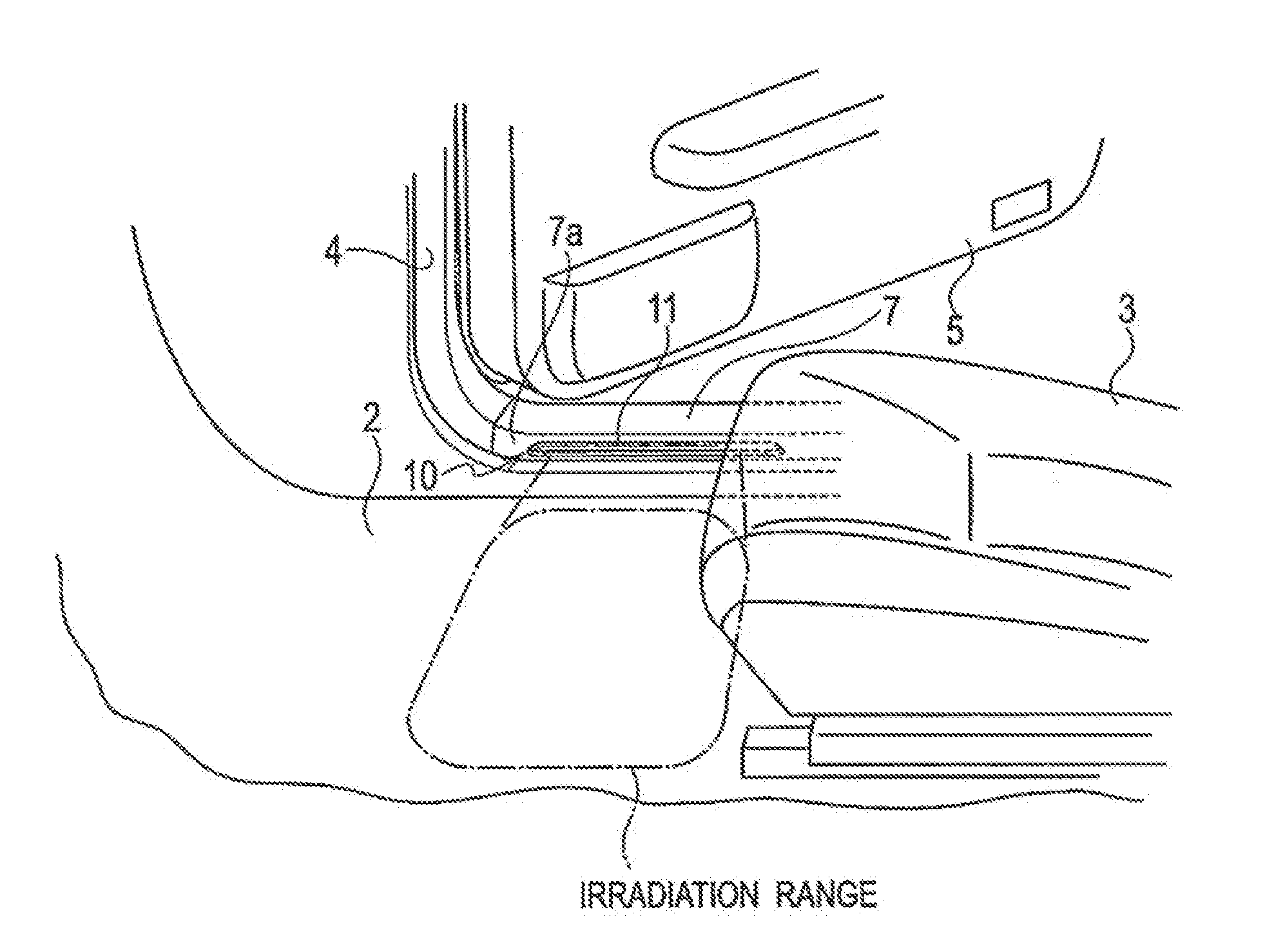
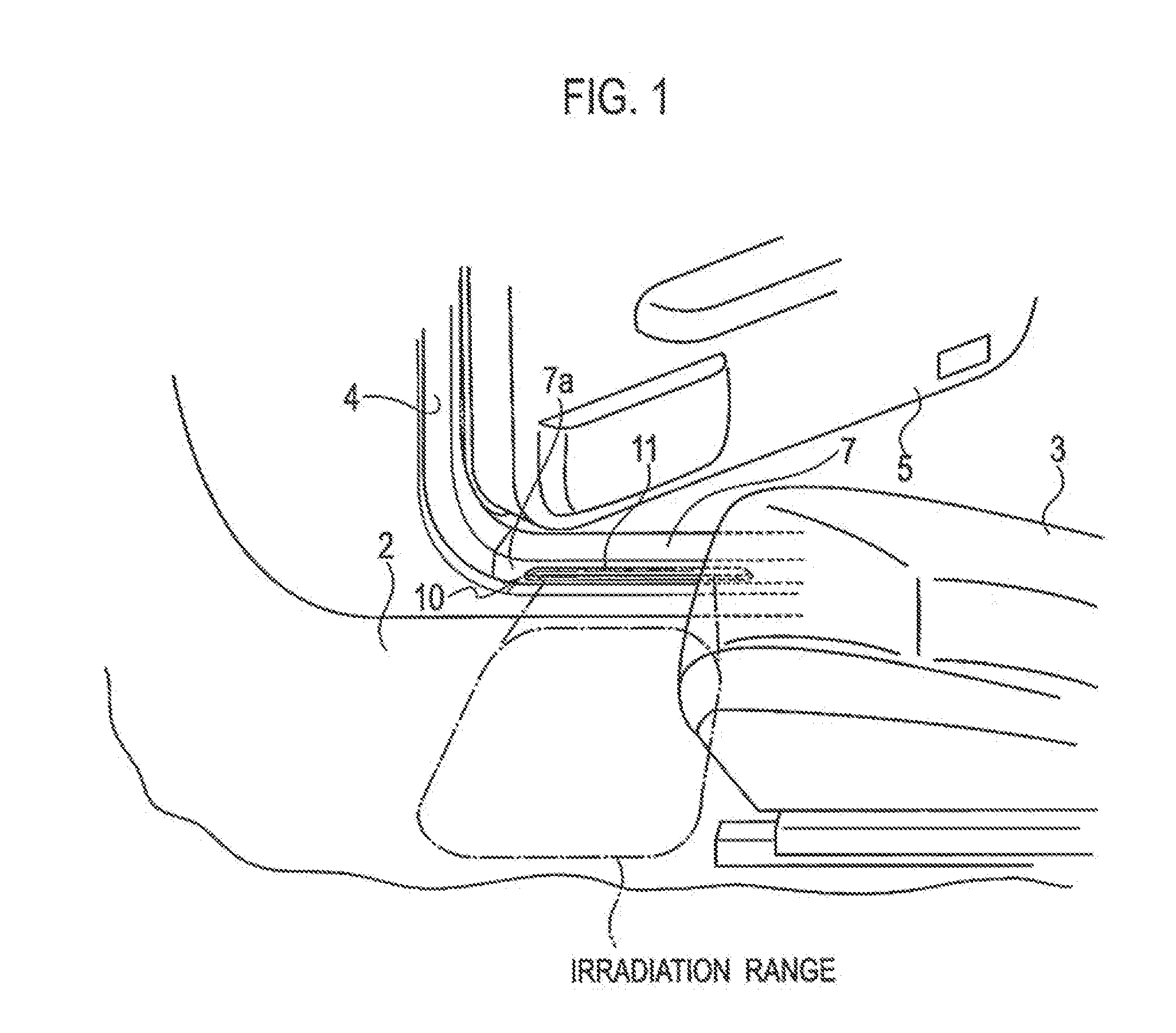
[0026]Hereinafter, a lighting device for a vehicle according to an embodiment is explained with reference to the drawings.

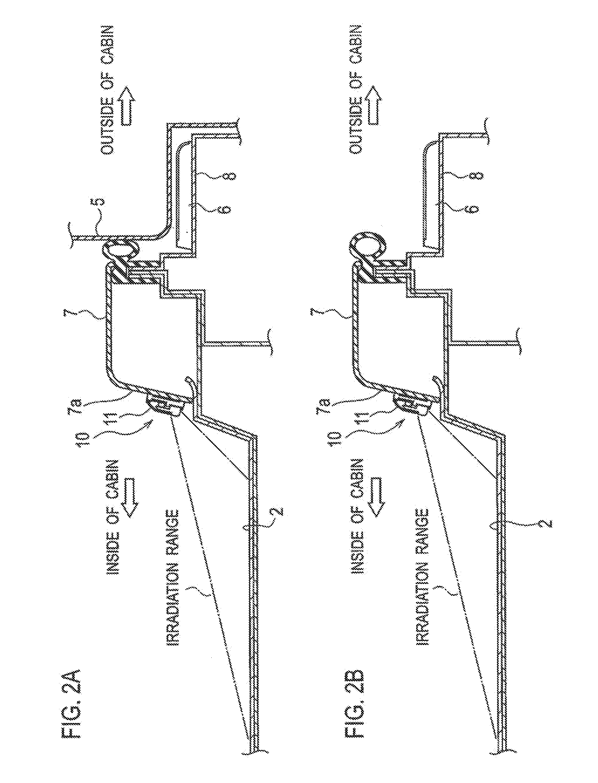
[0027]As shown in FIG. 1, FIG. 2A, FIG. 2B and FIG. 5, four seats 3 are provided on a floor 2 inside a cabin of the vehicle 1. Two of the seats 3 are provided on a front side and remaining two of the seats 3 are provided on a rear side. Door openings 4 are provided on sides of the vehicle 1 corresponding to the seats 3, respectively. The door openings 4 are opened or closed by doors 5, respectively. Kicking plates 6 are fixed to an outer body panel 8 below the door openings 4, respectively. Inner sill covers 7 are fixed to the floor 2 at positions closest to a cabin inner side of the kicking plates 6, respectively. Each of the inner sill covers 7 is arranged parallel to each of the kicking plates 6. The inner sill covers 7 are located higher than the kicking plates 6, respectively.

[0028]A lighting device 10 includes four inner sill lamps (floor lamps) 11. The inn...


PUM


Abstract

A lighting device for a vehicle includes inner sill lamps that illuminate a floor in a cabin. Each of the inner sill lamps is provided on each side surface of inner sill covers. The side surfaces faces to the cabin. The lighting device can sufficiently illuminate the floor without illuminance reduction due to an object such as an instrument panel or a seat disposed between the inner sill lamps and the floor. In addition, the lighting device can surely illuminate the floor around a user's feet when the user gets in or off the vehicle.

Description

CROSS-REFERENCE TO RELATED APPLICATION[0001]This application is based upon and claims the benefit of Japanese Patent Application No. 2009-262979, filed on Nov. 18, 2009; the entire contents of which are incorporated herein by reference for all purposes.BACKGROUND OF THE INVENTION[0002]1. Field of the Invention[0003]The present invention relates to a lighting device for a vehicle, and more particularly to a lighting device for lighting floor in a cabin.[0004]2. Description of the Related Art[0005]As a conventional lighting device for a vehicle, various types of devices that illuminate a cabin floor have been proposed. Japanese Utility Model Application Laid-Open No. S58-124346 (Patent document 1) and Japanese Patent Application Laid-Open No. H4-129856 (Patent document 2) disclose lighting devices that is a foot lamp mounted on a lower portion of an instrument panel. Japanese Utility Model Application Laid-Open No. H6-33738 (Patent document 3) discloses a lighting device that is a foo...

Claims


Application Information

Patent Timeline
Patent Type & Authority Applications(United States)
IPC IPC(8): B60Q1/14B60Q1/00
CPCB60Q3/0216B60Q3/0293B60Q3/0279B60Q3/74B60Q3/217B60Q3/80
Inventor SHIRATSUCHI, MASANORITANABE, YOSHITAKATAKANO, YOUICHI
Owner FALTEC CO LTD
Why Eureka
Try Eureka