Light source device and image display device

a light source and image technology, applied in the direction of static indicating devices, lighting and heating apparatuses, instruments, etc., can solve the problems of short lifetime as light sources, difficult maintenance, mercury in lamps, etc., and achieve long lifetime, high image quality, and high efficiency

Active Publication Date: 2013-04-11
PANASONIC CORP
View PDF2 Cites 97 Cited by
  • Summary
  • Abstract
  • Description
  • Claims
  • Application Information

AI Technical Summary

Benefits of technology

[0023]With the present technology, a bright, highly efficient light source device can be obtained by using a solid-state light source that does not har

Problems solved by technology

However, when a high-pressure mercury lamp is used as the light source, there is an environmental drawback in that the lamp contains mercury, which is a hazardous substance.
Another problem with high-pressure mercury lamps is that they have a short lifetime as a light source, and they are difficult to maintain.
Nevertheless, because of its high interference, a problem with laser light is that speckle noise is produced, which adversely affects image quality.
However, with an LED light source, the emission surface area of the light source is large, and the optical energy density of a green LED is particularly low.
Accordingly, with an LED light source, at present it is difficult to obtain a high-brightness image display device using LED's of three colors (red, green, and blue).
However, if the spot diameter of the laser beam condensed or focused on the phosphor is made too small, this will result in a problem in that the temperature of the phosphor increases and the emission efficiency of the fluorescent light decreases.
This is called temperature quenching, and is a s

Method used


Image

  • Light source device and image display device
  • Light source device and image display device
  • Light source device and image display device

Examples


first embodiment

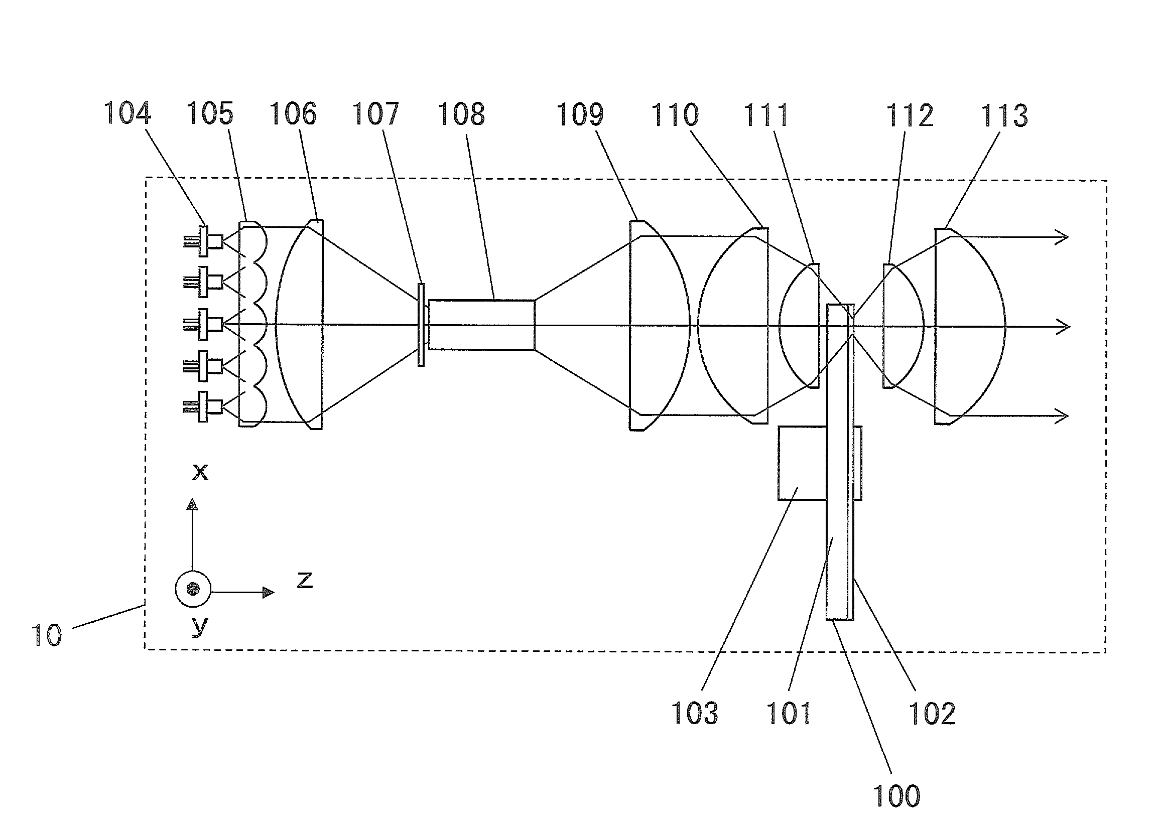
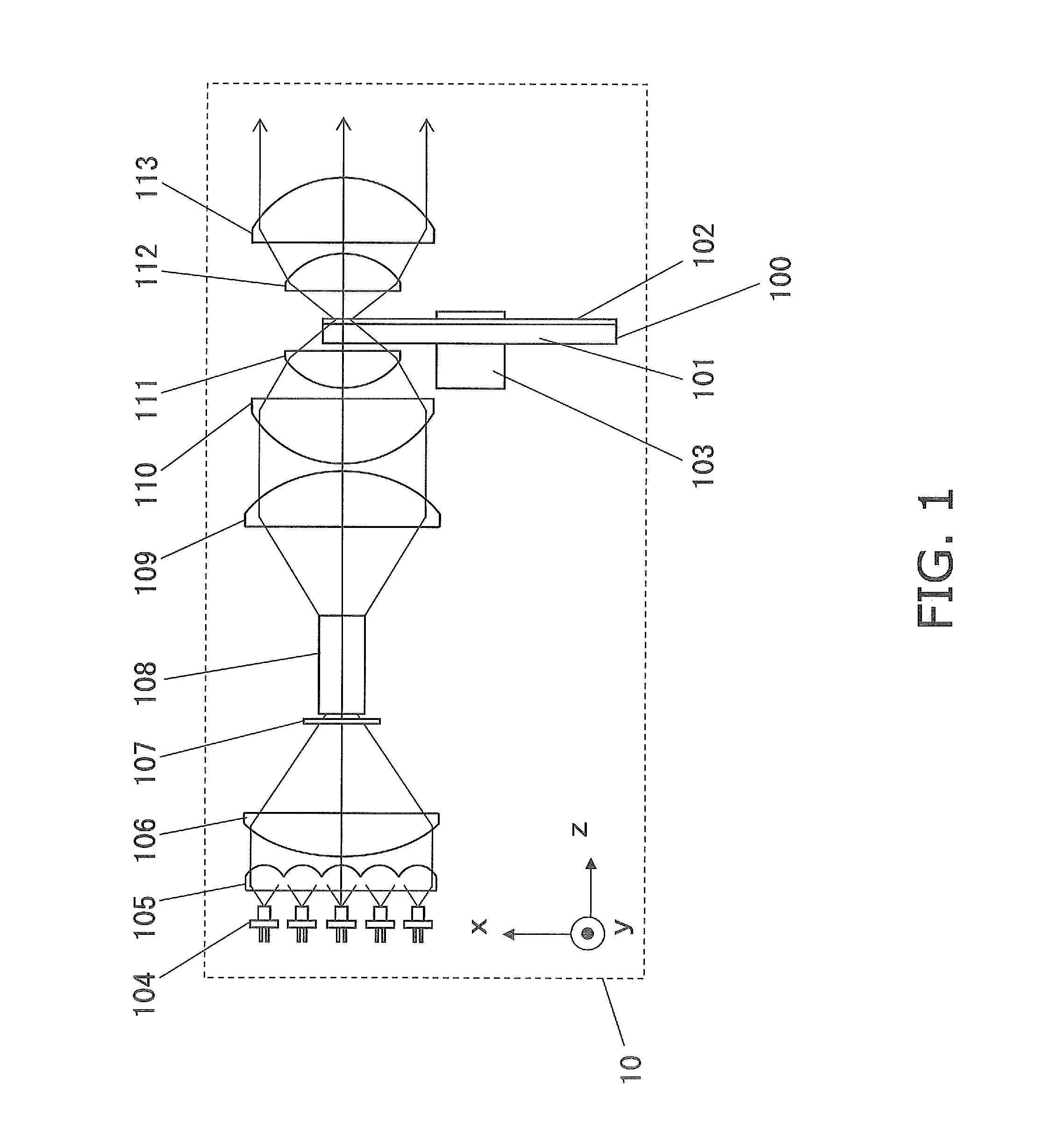
[0037]FIG. 1 is a diagram of the configuration of the light source device 10 pertaining to a first embodiment. The output light from the light source device 10 is made up of fluorescent light. The output light of the light source device 10 can be used as illumination light for an image display device or the like.

[0038]A laser light source 104 (an example of a first light source component) is a blue semiconductor laser that oscillates at a wavelength of approximately 445 nm. The laser light source 104 is made up of a plurality of semiconductor lasers to obtain a light source device of high brightness. In this embodiment, a total of 25 semiconductor layers are arranged in a 5×5 matrix. However, the number of semiconductor lasers is not limited to what is used in this embodiment, and may be suitably set according to the optical intensity of the semiconductor lasers, the intensity of the output light to be taken off from the light source device, and so on.

[0039]Nor is the wavelength of ...

second embodiment

[0061]FIG. 3 is a diagram of the configuration of the light source device 30 pertaining to a second embodiment. The output light of the light source device 30 is made up of three colors of visible light: red, green, and blue. The output light of the light source device 30 can be used as illumination light for an image display device or the like. Some of the constituent elements in this embodiment are the same as the constituent elements in first embodiment, and redundant descriptions will be eliminated in the following.

[0062]A laser light source 304 (an example of a first light source component), a collimator lens array 305, a focusing lens or a condensing lens 306, and a diffuser plate 307 are the same as in the first embodiment. Here again, the laser light flux that has passed through the diffuser plate 307 is incident on a first rod integrator 308 (an example of a first illuminance homogenizer).

[0063]The first rod integrator 308 is similar to the rod integrator 108 in the first e...

third embodiment

[0089]FIG. 4 is a diagram of the configuration of the light source device 40 pertaining to a third embodiment. The output light of the light source device 40 is made up of visible light of three time segments of periodically switched red light, green light, and blue light. The output light of the light source device is used as illumination light for an image display device or the like.

[0090]The constituent elements from a laser light source 405 (an example of a first light source component) to a collimating lens 410 are the same as the constituent elements in the second embodiment, and therefore will not be described again.

[0091]A dichroic mirror 411 (an example of a first color separator) is disposed tilted at approximately 45 degrees with respect to the optical axis of the laser light flux. The dichroic mirror 411 is highly transmissive to P polarization and highly reflective to S polarization in the laser light wavelength band, and is highly reflective regardless of the polarizat...


PUM


Abstract

The light source device includes a first light source component, a fluorescent component, a first illuminance homogenizer, and a relay optical system. The first light source component emits laser light. The fluorescent component has a phosphor. The phosphor is excited by laser light. The first illuminance homogenizer converts the laser light into laser light showing a spatially uniform light intensity distribution. The first illuminance homogenizer is disposed between the first light source component and the fluorescent component. The relay optical system guides laser light emitted from the first illuminance homogenizer to the fluorescent component. The relay optical system is disposed between the first illuminance homogenizer and the fluorescent component.

Description

CROSS-REFERENCE TO RELATED APPLICATIONS[0001]This application claims priority under 35 U.S.C. §119 to Japanese Patent Application No. 2011-221609, filed on Oct. 6, 2011 and No. 2012-185652, filed on Aug. 24, 2012. The entire disclosure of Japanese Patent Application No. 2011-221609 and No. 2012-185652 are hereby incorporated herein by reference.BACKGROUND[0002]1. Technical Field[0003]The technology disclosed herein relates to a light source device featuring a laser and a phosphor, and more particularly relates to a light source device that emits visible light such as red, green, blue, or other that is used in an image display device.[0004]2. Background Information[0005]Projectors are widely used as image display devices for projecting and enlarging various kinds of video or the like onto a screen. With a projector, light emitted from a light source is condensed or focused by a spatial light modulation element (a DMD (digital micromirror device) or a liquid crystal display element). ...

Claims


Application Information

Patent Timeline
IPC IPC(8): F21V13/02G09G5/00
CPCH04N9/3114H04N9/3161G03B21/2013G03B33/12G03B21/2073G03B21/208G03B21/204G02B26/008G02B27/1026
Inventor KITANO, HIROSHI
Owner PANASONIC CORP
Why Eureka
Try Eureka