Driver's appearance recognition system

a technology of appearance recognition and driver, which is applied in the field of driver appearance recognition system, can solve the problems of unpreferable methods, and shortening so as to prolong the service life of infrared light radiation and reduce current

Inactive Publication Date: 2005-10-13
DENSO CORP
View PDF3 Cites 100 Cited by
  • Summary
  • Abstract
  • Description
  • Claims
  • Application Information

AI Technical Summary

Benefits of technology

[0033] An image may be captured for the second driver's appearance recognition process not requiring so high illumination intensity as the first driver's appearance recognition process. In such case, the present invention can decrease the amount of current supplied to the infrared light radiation means compared to the system not having the current amount control means.
[0034] As a result, the present invention can extend the service life of the infrared light radiation means compared to the system not having the current amount control means.

Problems solved by technology

Such technologies cause the following problem.
Generally, applying large currents shortens the service life of the infrared light radiation means such as the light emitting diode.
When a vehicle is equipped with the system to perform the individual authentication and the closed-eye detection using face images, the service life of the infrared light radiation means becomes short.
The problem also occurs in a system to perform a plurality of appearance authentications differing in necessary illumination intensities on face images used for the driver's appearance recognition.
The problem becomes particularly remarkable for the case of equipping a vehicle with the individual authentication system and the closed-eye detection.
However, this method is unpreferable because the infrared light radiation means generates low illumination intensity and decreases the detection accuracy during the individual authentication.

Method used


Image

  • Driver's appearance recognition system
  • Driver's appearance recognition system
  • Driver's appearance recognition system

Examples


first embodiment

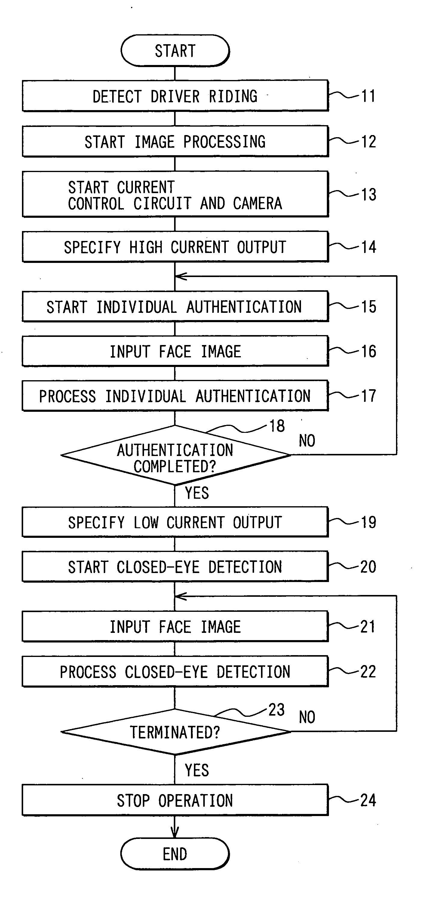
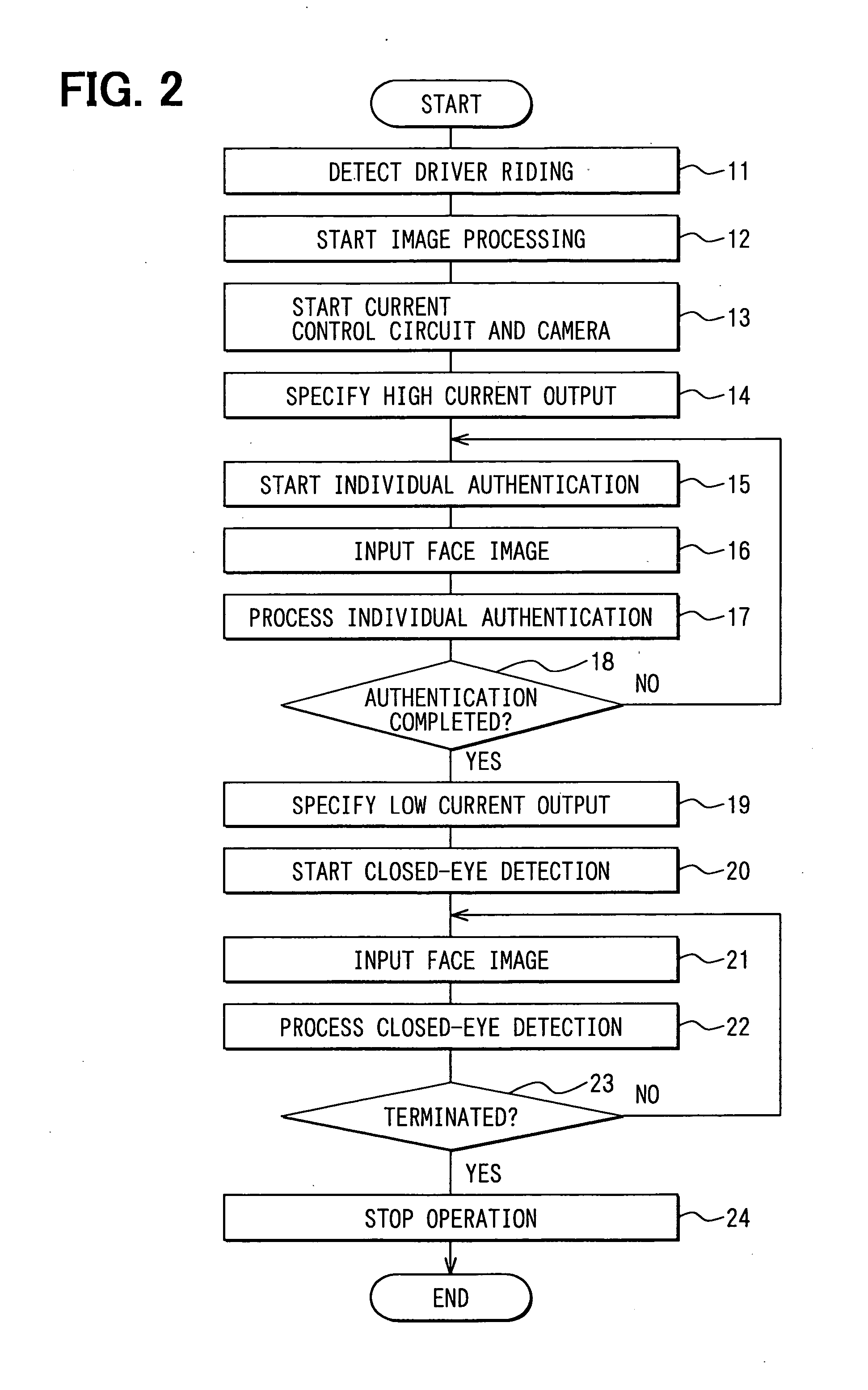
[0041] The driver's appearance recognition system according to the embodiment performs individual authentication and closed-eye detection.

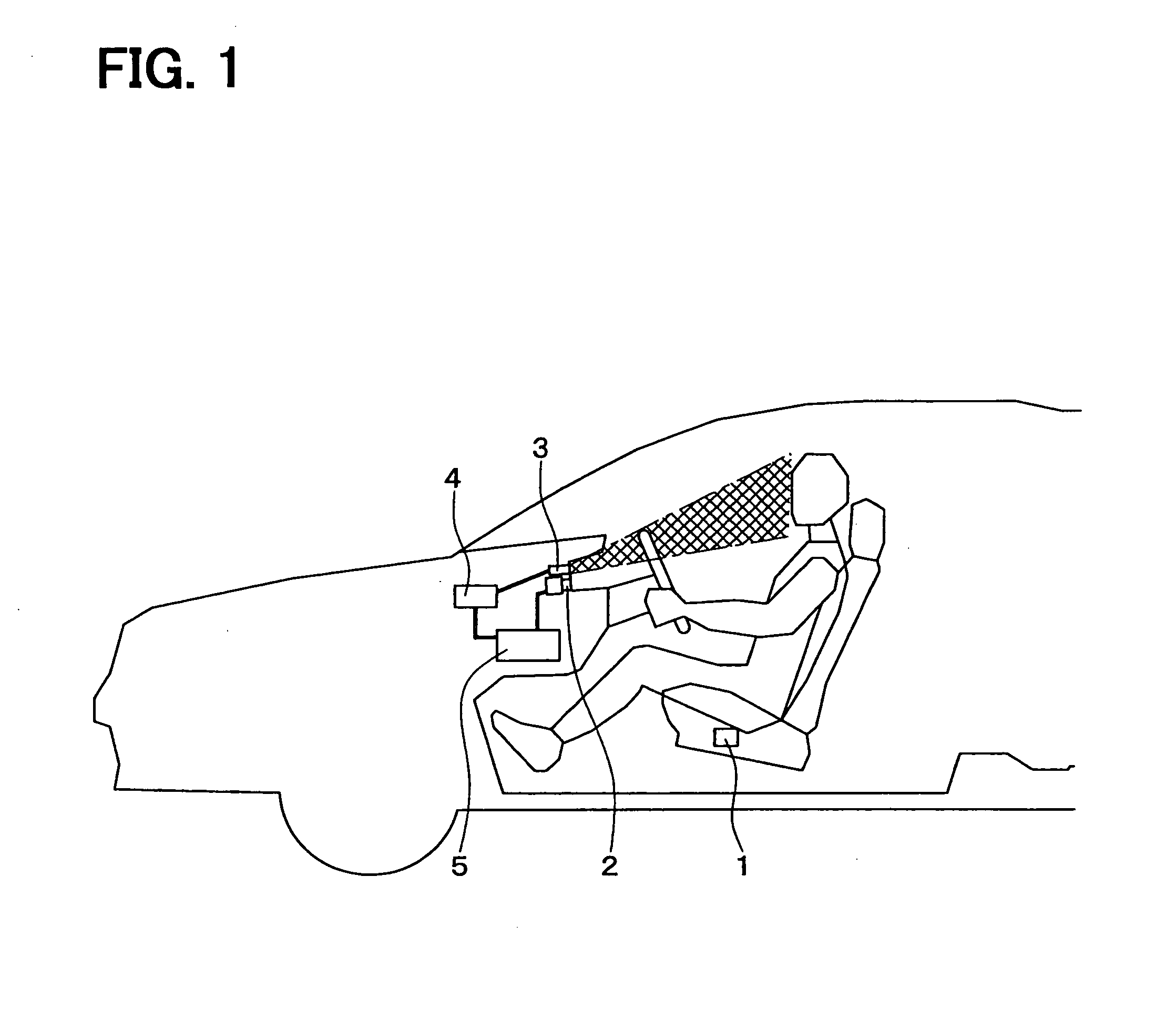
[0042]FIG. 1 shows the configuration of the driver's appearance recognition system according to a first embodiment of the present invention. As shown in FIG. 1, the system comprises a weight detection switch 1 as riding detection means; a camera 2; a near infrared ray light emitting diode 3 as infrared light radiation means; a near infrared ray light emitting diode's current control circuit 4 as current amount control means; and an image processing circuit 5 as appearance recognition control means. In the following description, the near infrared ray light emitting diode 3 is referred to as the near infrared ray LED 3. The near infrared ray light emitting diode's current control circuit 4 is referred to as the LED current control circuit 4.

[0043] The weight detection switch 1 detects the presence of a driver and is built in a driver's seat surfac...

second embodiment

[0096] This embodiment adds a timer function to the image processing circuit 5 according to the first embodiment. That is, the second embodiment supplements the image processing circuit 5 with a function to monitor the continuation time of the individual authentication process. The timer measures a time lapse from Step 15.

[0097] The first embodiment described the example where the image processing circuit 5 executes the individual authentication process for the purpose of permitting the engine to start. The second embodiment will describe an example where the image processing circuit 5 executes the individual authentication process for the purpose of conforming the environment of in-vehicle units to user's requirements.

[0098]FIG. 3 shows a flowchart of the driver's appearance recognition process executed by the image processing circuit 5 according to the second embodiment of the present invention.

[0099] The driver's appearance recognition process for the image processing circuit ...

third embodiment

[0108]FIG. 4 shows the configuration of the driver's appearance recognition system according to a third embodiment of the present invention. When the driver drives the vehicle in the daytime, the outside light is normally radiated to the driver's face. When the near infrared ray LED 3 radiates the infrared light to the driver, the outside light and the infrared light from the near infrared ray LED 3 are radiated to the driver's face. When the outside light illuminance is high, sufficient illumination intensity is available from the driver's face despite reduction of the illumination intensity for the near infrared ray LED 3.

[0109] The third embodiment adds an outside light illuminance sensor 6 to the system according to the first embodiment of the present invention. The third embodiment further adds a control function to the image processing circuit 5 and the LED current control circuit 4 according to the first embodiment. This control function suppresses the amount of current supp...


PUM


Abstract

A driver's appearance recognition system comprises: a camera to capture a driver's face image; a near infrared ray LED to radiate near infrared ray to the driver's face; an LED current control circuit to control the amount of current supplied to the near infrared ray LED; and an image processing circuit to execute an individual authentication process and a closed-eye detection process. When the individual authentication process is executed, it is necessary to increase the illumination intensity during image capture by the camera. For this purpose, a setup current value for the LED current control circuit is set to a high current value. When the closed-eye detection process is executed, the illumination intensity needs to be ensured as much as required for the closed-eye detection process. For this purpose, a setup current value is set to a current value lower than that used for execution of the individual authentication process.

Description

CROSS REFERENCE TO RELATED APPLICATIONS [0001] This application is based on and incorporates herein by reference Japanese Patent Application No. 2004-117931 filed on Apr. 13, 2004. FIELD OF THE INVENTION [0002] The present invention relates to a system to recognize driver's appearance using a vehicle driver's face image captured by a camera. For example, the present invention is used for car antitheft systems, usability improvement systems, or accident prevention systems. BACKGROUND OF THE INVENTION [0003] Conventionally, there are known car antitheft systems, usability improvement systems, and accident prevention systems. As will be discussed below, such systems recognize driver's appearance for individual authentication, closed-eye detection, and the like using vehicle driver's face images captured by a camera. [0004] For example, an individual authentication system using face images extracts a pupil's iris pattern from driver's face images captured by a camera. The system collate...

Claims


Application Information

Patent Timeline
Patent Type & Authority Applications(United States)
IPC IPC(8): A61B5/117B60R25/25G06K9/00G06T1/00G06T7/20G08B13/194G08G1/16
CPCB60R25/25G06T1/00G06K9/00228B60R25/255G06V40/161
Inventor KOMURA, TAKASHI
Owner DENSO CORP
Why Eureka
Try Eureka