
White light source device

a light source and white light technology, applied in the direction of lighting and heating apparatus, semiconductor devices for light sources, instruments, etc., can solve the problems of low white light output efficiency, high rate of light absorption, easy exit, etc., to achieve uniform color, suppress color separation, and enhance light uniformity

Inactive Publication Date: 2008-09-25
NEC LIGHTING
View PDF6 Cites 102 Cited by
  • Summary
  • Abstract
  • Description
  • Claims
  • Application Information

AI Technical Summary

Benefits of technology

[0010]An object of the present invention is to provide a white light source device capable of reducing unevenness of color by combining a light emitting element and a sheet in which fluorescent material is dispersed.
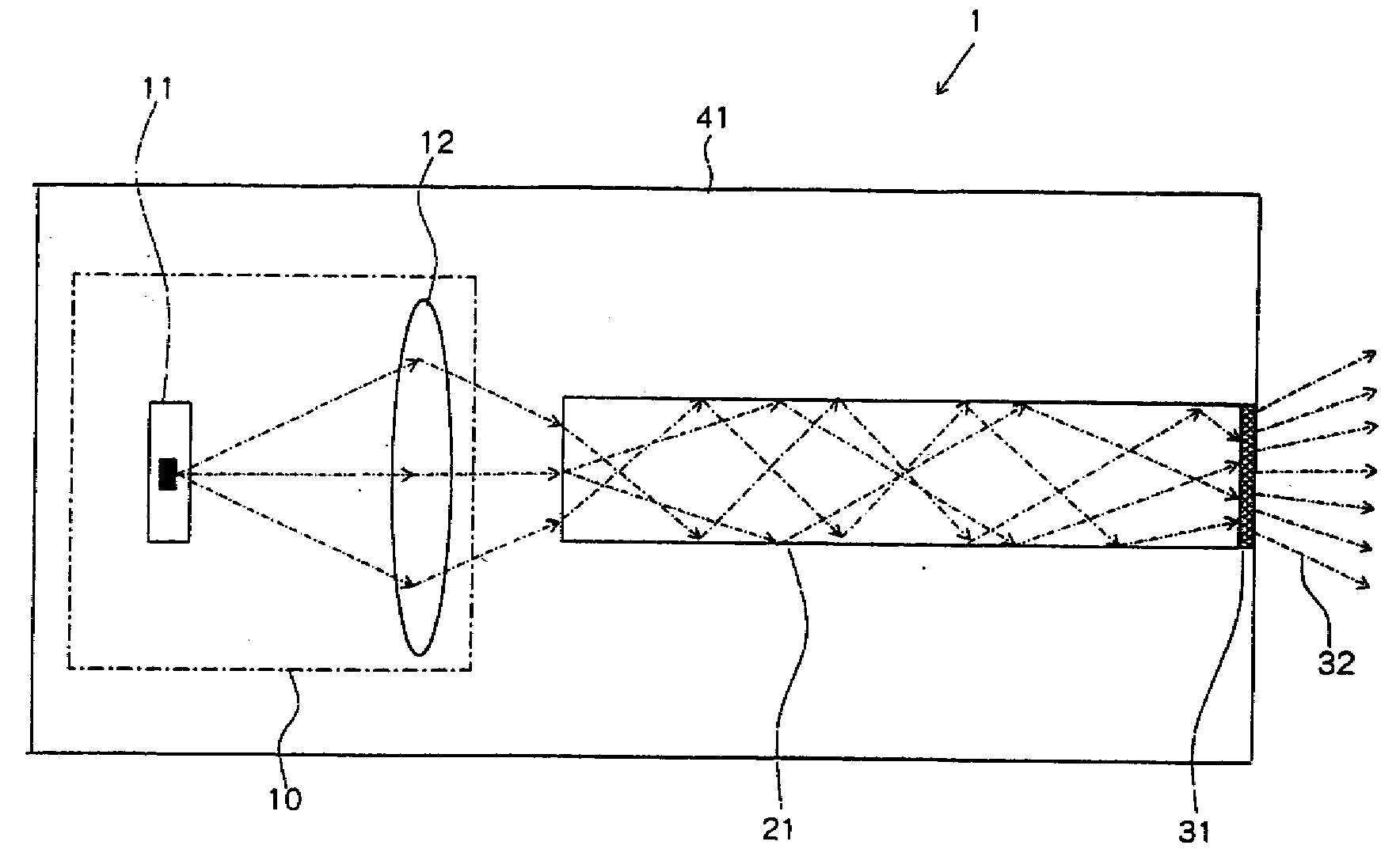
[0016]A rod lens, which intervenes in the path of highly directive light from an LED, enhances light uniformity at an exit face of the rod lens, and this light that was uniformized, is illuminated directly on the fluorescent material sheet, which can provide white light which is evenly colored.
[0017]According to the present invention, because the rod lens is placed between the LED light source and the sheet in which fluorescent material is dispersed, highly uniform light can be illuminated on the fluorescent material sheet to suppress color separation in the fluorescent material sheet, which can provide white light without unevenness of color.

Problems solved by technology

In the white light source having such a structure, the output efficiency of the white light was low, because of large absorption of light in the blue light emitting element and the fluorescent material.
In the blue light emitting element, the light cannot be easily exited outside again because of the high refractive index, resulting in high rate of absorption of the light.
Further, a considerable part of the light entering a fluorescent material layer is absorbed in the fluorescent material layer, resulting in low light output efficiency for the white light emitted from the fluorescent material layer.
However, the configuration disclosed in Japanese Patent Laid-Open No. 2005-99328 does not have a fluorescent material sheet provided therein.
However, Japanese Patent Laid-Open No. 2005-339853 does not describe a configuration in which exiting light from the blue LED enters the fluorescent substance through the rod lens.
Accordingly, in the case of an LED, it is difficult to control light distribution by using a reflector, compared to the case of an electric bulb.
According to the method by which the sheet in which fluorescent material is dispersed is placed away from the light emitting element to provide a white light source, light from an LED is not uniformly illuminated on a surface of the sheet, and considerable unevenness of color is generated between the central portion and the end portion.
Unevenness of color is a serious problem especially when the white light is used for general illumination, so that the unevenness of color has to be reduced as much as possible.

Method used


Image

  • White light source device
  • White light source device
  • White light source device

Examples


Embodiment Construction

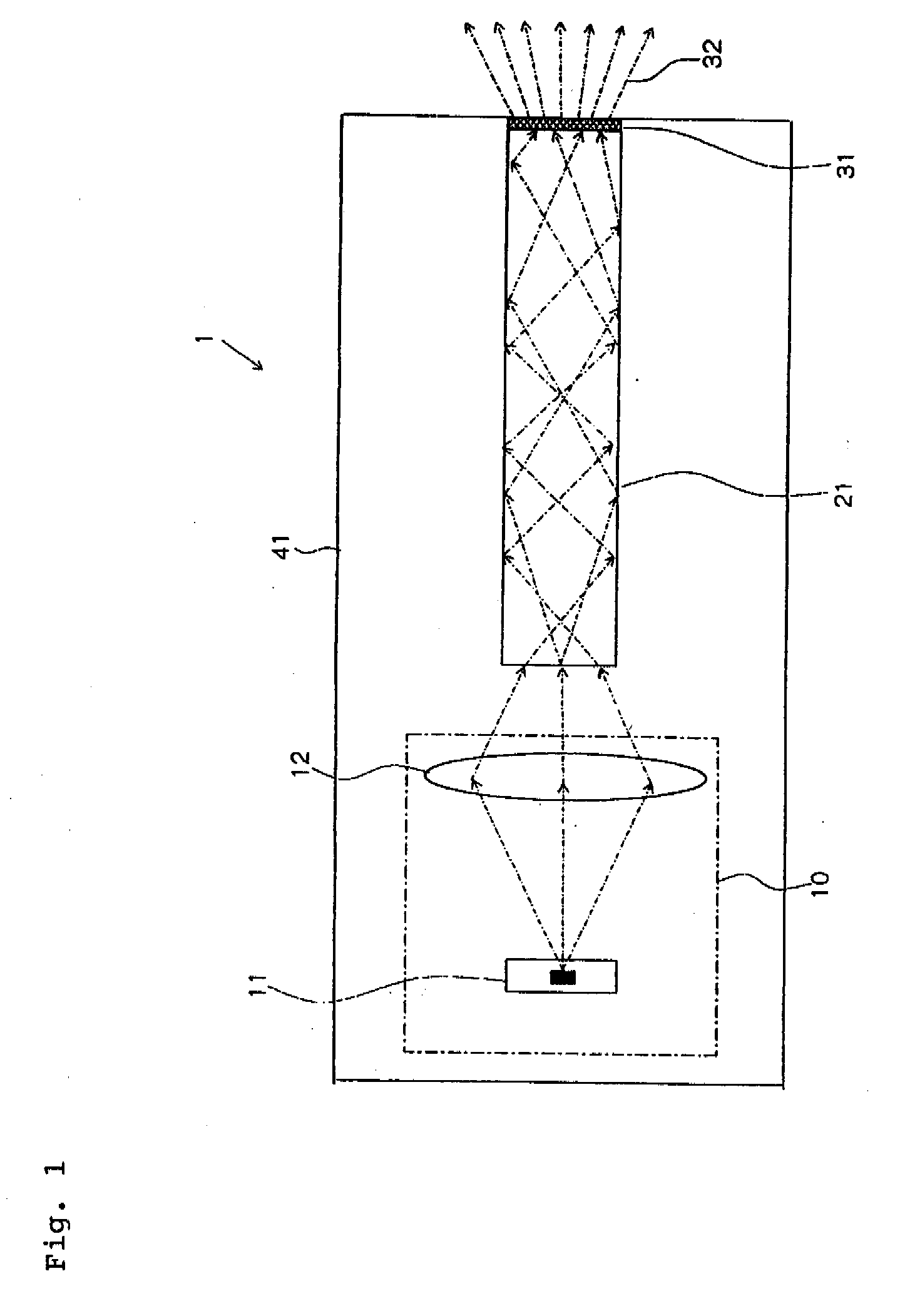
[0021]Now, exemplary embodiments of the present invention will be hereinafter described with reference to the accompanying drawings. FIG. 1 is a side view schematically illustrating a white light source device of a first exemplary embodiment.

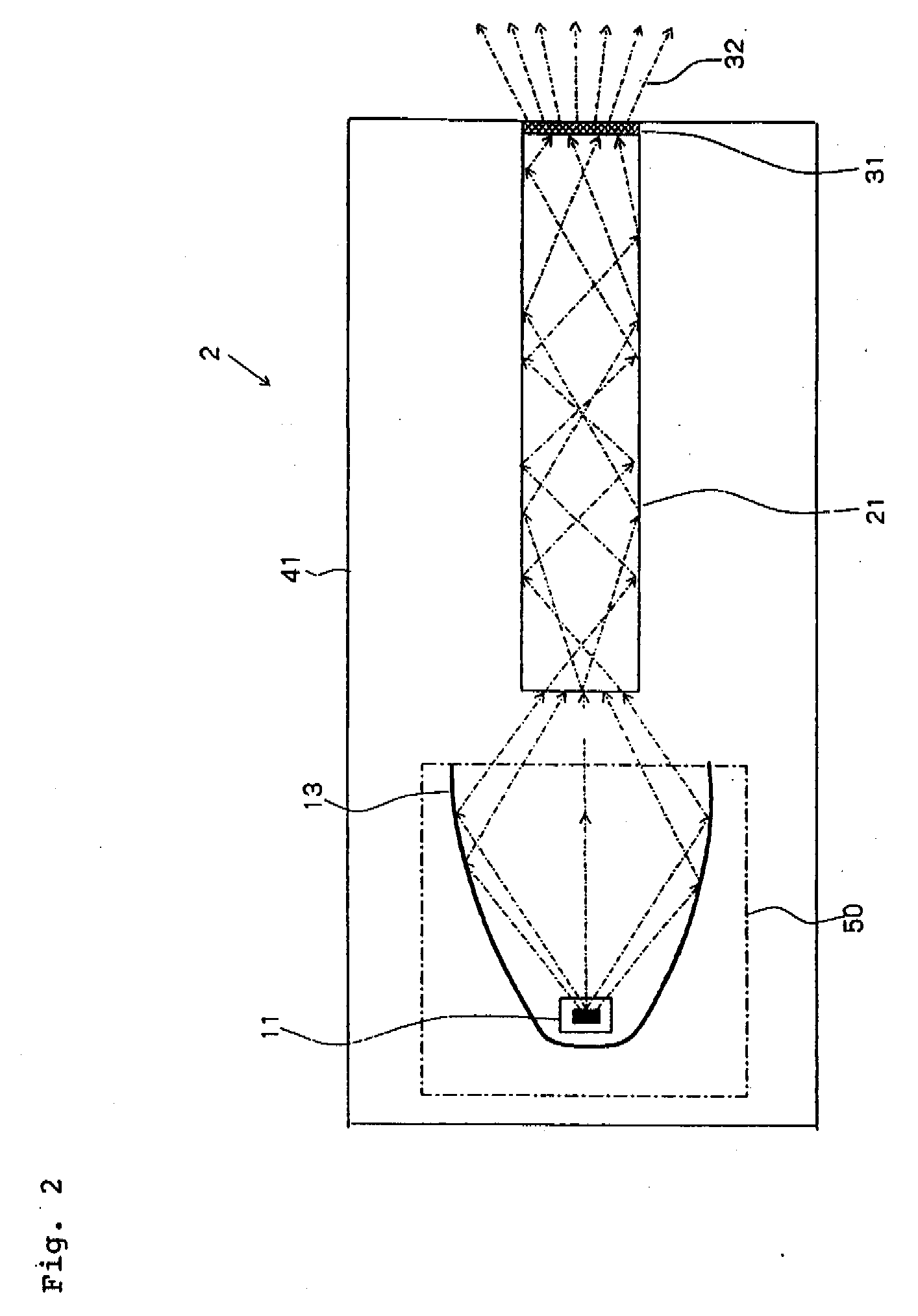
[0022]White light source device 1 of the first exemplary embodiment includes: light source unit 10 including blue LED light source 11 composed of a blue LED and condenser lens 12 for condensing blue light beams emitted from blue LED light source 11 on an entrance face of rod lens 21; rod lens 21; fluorescent material sheet 31 bonded to an exit face of rod lens 21; and casing 41 for forming a chassis.

[0023]Electric current is supplied by a power supply not shown in the figure through a switch to blue LED light source 11. Rod lens 21 is a transparent body having a quadratic prism shape, and an inner face of an outer circumferential wall thereof is configured to be a reflecting face. A light beam that entered rod lens 21 progresses while occasional...


PUM


Abstract

Light beams emitted from a blue LED light source of a light source unit are condensed by a condenser lens to enter an entrance end face of a rod lens, and the light beams progress through while being repeatedly reflected several times inside the rod lens. Accordingly, the unevenness of brightness is reduced, and the light enters an fluorescent material sheet bonded to an exit end of the rod lens from the exit end as blue light which is uniformed in illuminance, and white light whose color is seen as the same color viewed in any direction of the fluorescent material sheet is emitted from the fluorescent material sheet.

Description

[0001]This application is based upon and claims the benefit of priority from Japanese patent application No. 2007-070546, filed on Mar. 19, 2007, the disclosure of which is incorporated herein in its entirety by reference.BACKGROUND OF THE INVENTION[0002]1. Field of the Invention[0003]The present invention relates to a white light source device, and particularly to a white light source device including a rod lens.[0004]2. Description of the Related Art[0005]Conventionally, there has been a white light source that emits white light by mixing blue light emitted from a blue light emitting element, which is sealed with a transparent binder containing fluorescent material, with excited light emitted from the fluorescent material on which the blue light fell. In the white light source having such a structure, the output efficiency of the white light was low, because of large absorption of light in the blue light emitting element and the fluorescent material. A considerable part of the lig...

Claims


Application Information

Patent Timeline
Patent Type & Authority Applications(United States)
IPC IPC(8): F21V9/16H01L33/50F21V9/40H01L33/58H01L33/60
CPCG02B6/0003G02B6/4298F21Y2101/02F21V9/16F21K9/56F21K9/64F21V9/38F21V13/14F21Y2115/10
Inventor KON, SHUSAKU
Owner NEC LIGHTING
Learn More