Adjustable swivel fluid conduit pathway

a fluid conduit and swivel technology, applied in the direction of adjustable joints, pipe joints, mechanical equipment, etc., can solve the problems of inability to retain proper angles and coherence of existing fluid conduit pathways, and inability to provide a reliable fluid pathway, etc., to achieve easy installation and reduce system length , the effect of easy transportation

Inactive Publication Date: 2011-05-26
KAPLAN IRA HAROLD
View PDF4 Cites 4 Cited by
  • Summary
  • Abstract
  • Description
  • Claims
  • Application Information

AI Technical Summary

Benefits of technology

[0011]Still another advantage of the present adjustable swiveled fluid conduit system is that the system may be expanded or reduced in length easily.
[0012]And another advantage of the present adjustable swiveled fluid conduit system is that the system maintains a much more coherent jet when existing the nozzle end than other adjustable swiveled fluid conduit systems.
[0013]And another advantage of the present adjustable swiveled fluid conduit system is that the system may be installed easily and quickly.
[0014]An advantage of the present adjustable swiveled fluid conduit system is that the system may be transported easily.
[0015]In an embodiment, the adjustable swiveled fluid conduit is easily extended or shortened by the addition or removal of some of the ball joint connectors.
[0016]In yet another embodiment, the adjustable swiveled fluid conduit may be easily secured at alternative predetermined angles.

Problems solved by technology

The problem with many past fluid conduit connector devices is that they fail to provide a reliable fluid pathway which can be secured under the mid to higher pressures required for the operation of certain grinding and milling machines and machining centers.
In addition, existing fluid conduit pathways made up of segments do not provide a manner in which to easily hold the geometry of pathway while still being able to change the conduit length easily.
Even further, existing fluid conduit pathways often do not retain their proper angles and coherence under the newer mid to high-pressure conditions.

Method used


Image

  • Adjustable swivel fluid conduit pathway
  • Adjustable swivel fluid conduit pathway
  • Adjustable swivel fluid conduit pathway

Examples


Embodiment Construction

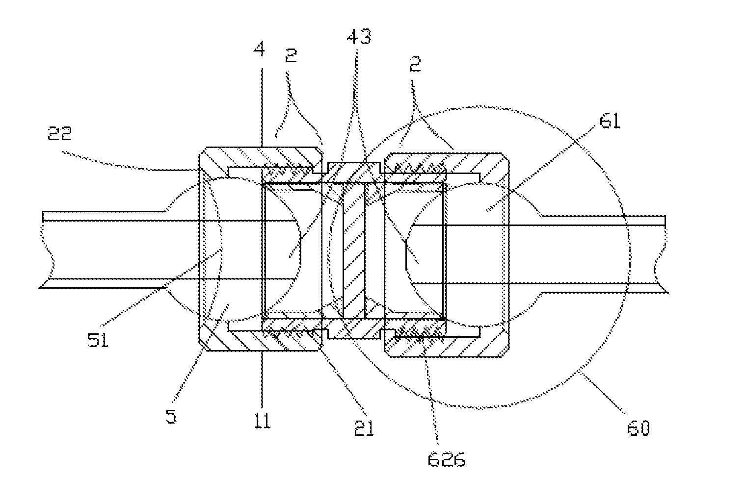
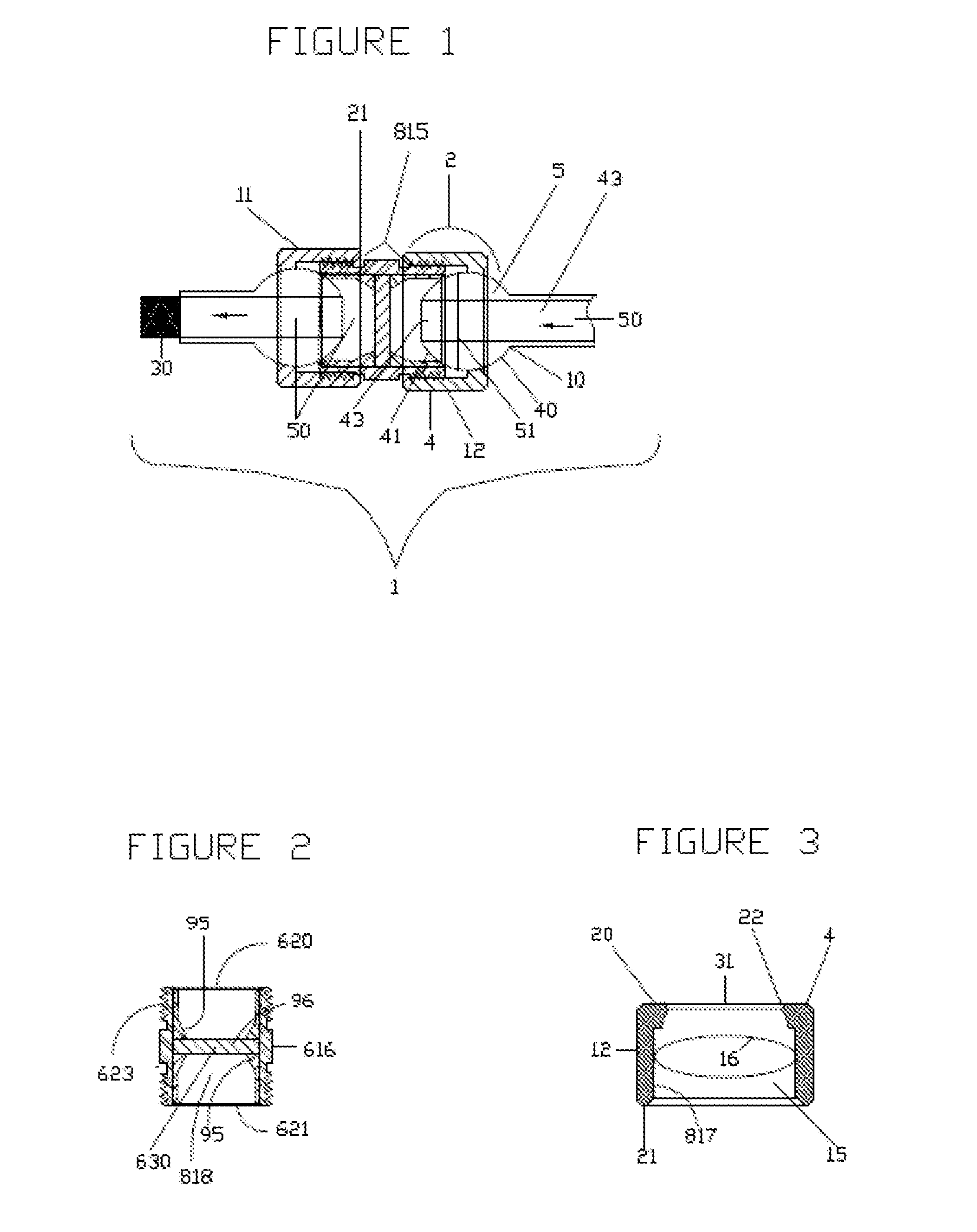
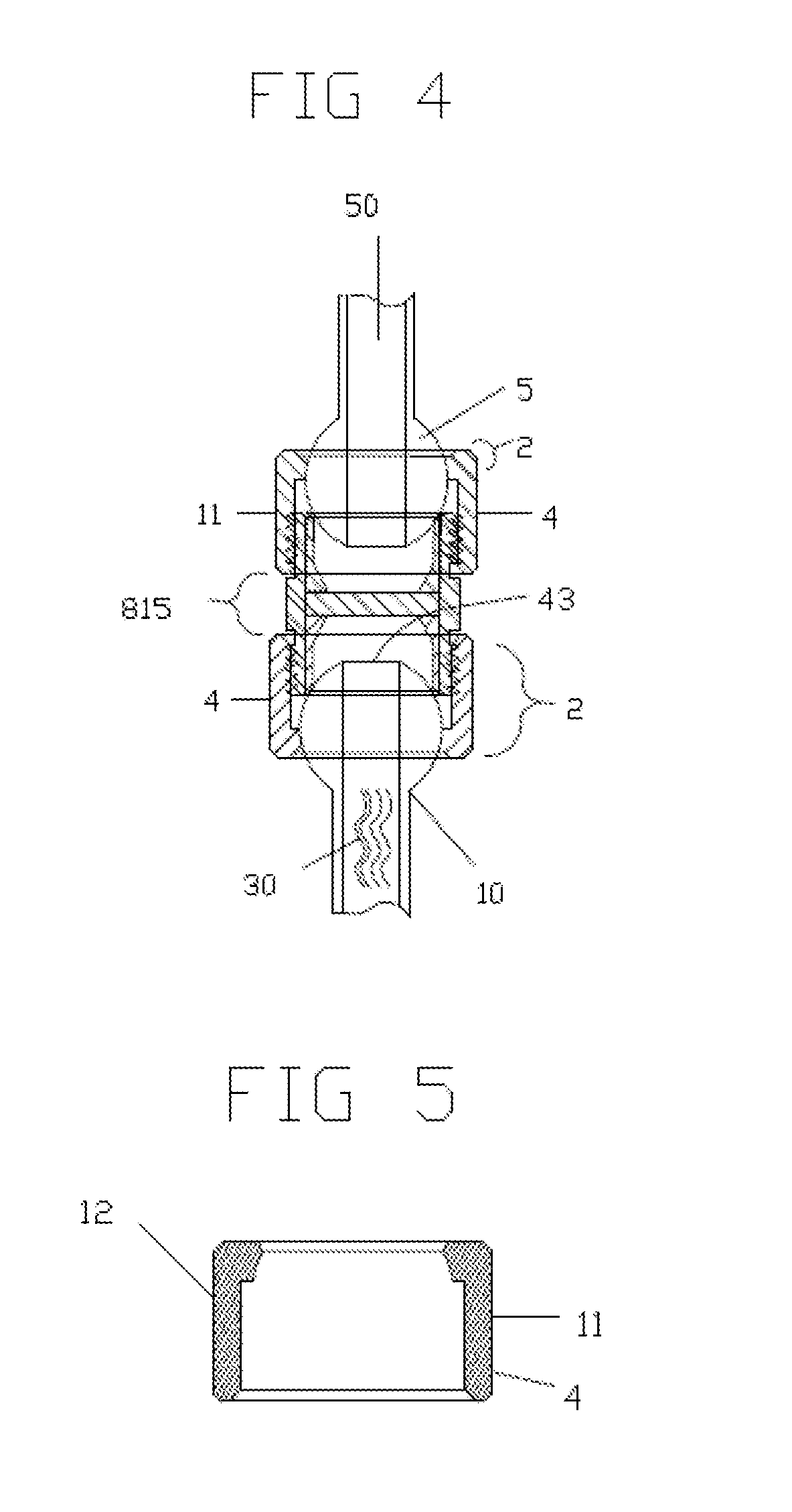
[0039]An adjustable swiveled fluid conduit pathway having a plurality of interconnecting joints for securing a pressurized fluid line in a predetermined path is provided. The adjustable swiveled fluid conduit pathway is particularly suitable for securing a mid to high-pressure coolant fluid line in, for example, a computer numerically controlled (CNC) grinding machine. A plurality of interconnecting joints comprise the pathway. The interconnecting joints each have two ball joint assembly units having an interior pathway for a fluid (aligned ball portion facing ball portion) and a nut housing unit. A washer is located, under pressure, between the two balls of the ball-joint assembly units. The adjustable swiveled fluid conduit pathway may be extended or shortened by the addition or removal of an interconnecting joint (or link). The adjustable swiveled fluid conduit pathway is secured in the pre-determined position by securing the interconnecting joints at a specific desired angle. Th...


PUM


Abstract

An adjustable swiveled fluid conduit pathway having a plurality of interconnecting joints for securing a pressurized fluid line in a predetermined path is provided. The adjustable swiveled fluid conduit pathway is particularly suitable for securing a mid to high-pressure coolant fluid line in, for example, a computer numerically controlled (CNC) grinding machine. A plurality of interconnecting joints comprise the pathway. The interconnecting joints each have two ball joint assembly units having an interior pathway for a fluid (aligned ball portion facing ball portion) and a nut housing unit. A washer and bushings are located, under pressure, between the two balls of the ball-joint assembly units. The adjustable swiveled fluid conduit pathway may be extended or shortened by the addition or removal of an interconnecting joint (or link). The adjustable swiveled fluid conduit pathway is secured in the pre-determined position by securing the interconnecting joints at a specific desired angle.

Description

CROSS REFERENCE TO RELATED APPLICATIONS[0001]The present application claims priority benefit of U.S. Provisional Application 61 / 281,762, filed on Nov. 23, 2009, which is hereby incorporated by reference in its entirety.BACKGROUND OF THE INVENTION[0002]An adjustable swiveled fluid conduit pathway having a plurality of interconnecting joints for securing a pressurized fluid line in a predetermined path is provided. The adjustable swiveled fluid conduit pathway is particularly suitable for securing a mid to high-pressure coolant fluid line in, for example, a computer numerically controlled (CNC) grinding machine. A plurality of interconnecting joints comprise the pathway. The interconnecting joints each have two ball-joint assembly units having an interior pathway for a fluid (aligned ball portion facing ball portion) and a nut housing unit. A washer is located, under pressure, between the two balls of the ball-joint assembly units. The adjustable swiveled fluid conduit pathway may be ...

Claims


Application Information

Patent Timeline
Patent Type & Authority Applications(United States)
IPC IPC(8): F16L27/04
CPCF16L27/113F16L27/047
Inventor KAPLAN, IRA HAROLD
Owner KAPLAN IRA HAROLD
Why Eureka
Try Eureka