
Linear Accelerators

a technology of linear accelerators and accelerators, which is applied in the field of linear accelerators, can solve the problems of inconvenient treatment for patients, inability to bring long process of bringing a new linac into service, so as to reduce the time for characterisation and testing, reduce the cost of treatment, and facilitate the booking of patients

Active Publication Date: 2011-05-26
ELEKTA AB
View PDF5 Cites 11 Cited by
  • Summary
  • Abstract
  • Description
  • Claims
  • Application Information

AI Technical Summary

Benefits of technology

[0008]We therefore propose that during the factory testing of the linac, rather than simply confirming that the beam falls within the permissible ranges set out in the standard, the beam is in fact adjusted towards a standard signature. This standard signature could then be published for use by writers of treatment planning software. As a result, while there may be small differences between the actual signature of the beam and the standard signature, these will take less time to characterise and test and therefore the linac can be brought into service more quickly.
[0010]In addition, the standard signature to which the linacs were approximated could be placed towards the centre of the permitted ranges. This could produce linacs that were more reliable over the very long term.

Problems solved by technology

As a result of these constraints, the process of bringing a new linac into service can be very lengthy.
During this time, the linac is not available for treatment of patients, which is (clearly) inconvenient for the clinic and for patients.

Method used


Image

  • Linear Accelerators
  • Linear Accelerators
  • Linear Accelerators

Examples


Embodiment Construction

1 Introduction

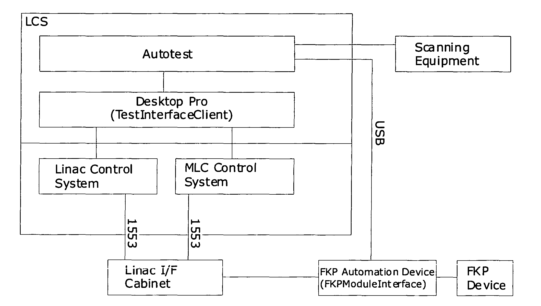
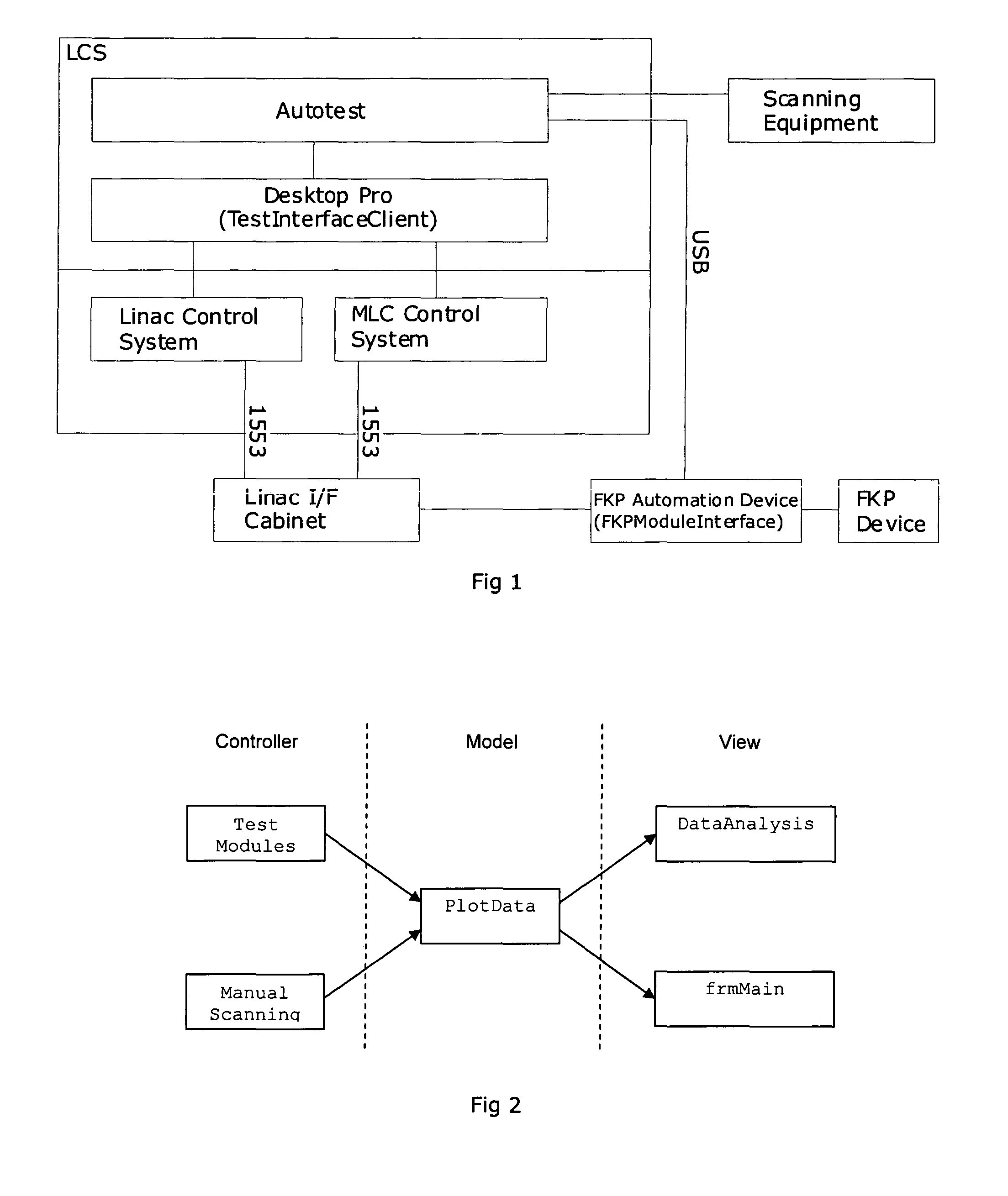
[0032]Referring to the accompanying figures, we will now describe our “Autotest” software and the relationships between its individual components, before going on to describe how this might be used in practice.

2 Overview

[0033]The Autotest software contains one executable file and several dynamic link libraries (DLLs) that fit together to produce a suite of test tools for shelter or in-use testing. By “shelter testing”, we mean the testing of a new linac that takes place immediately after manufacture. Generally, after assembly the new linac will be placed in a radiation-shielded area referred to as a “shelter”, within which it can be operated safely during initial testing.

[0034]To accomplish this, the software needs to be able to communicate directly to the Linac and also to scanning equipment placed in the beam that provides data characterising the beam. The Autotest software controls the linac via the Desktop Pro control system; two components are used to control the ...


PUM


Abstract

We propose that during the factory testing of the linac, rather than simply confirming that the beam falls within the permissible ranges set out in the standard, the beam is in fact adjusted towards a standard signature. A new (or existing) linac could then be paired to a new linac, or to an existing linac, such as one that it is to operate alongside or one that it is to replace. Treatment plans would then be transferable between such pairs of linacs. In addition, the standard signature to which the linacs were approximated could be placed towards the centre of the permitted ranges, to produce linacs that were more reliable over the very long term. This requires a linac that has automatically adjustable parameters, so that a suitable programmed computer is able to monitor the output of the linac and adjust its operating parameters. We therefore provide a radiation source comprising a linear accelerator, beam control circuitry for the linear accelerator, an electronic control apparatus for the control circuitry arranged to adjust properties thereof, and a monitor for detecting properties of the radiation beam produced by the linear accelerator, wherein the control apparatus is adapted to retain a set of beam properties and periodically activate the accelerator, measure the current beam properties via the monitor, compare the measured beam properties to the retained beam properties, and potentially adjust the control circuitry properties to align the beam properties towards the retained beam properties. The beam properties that are measured may include at least one of beam flatness and beam width. The retained beam properties can be the properties of the beam produced by the linear accelerator when new, or the properties of a standard beam. The control apparatus is preferably arranged to send a message if the difference between the measured beam properties and the retained beam properties exceeds a threshold. It may also send a message to a remote location if the difference between the measured beam properties and the retained beam properties exceeds a second threshold.

Description

FIELD OF THE INVENTION[0001]The present invention relates to the field of linear accelerators (“linacs”). It is especially, but not exclusively, concerned with such accelerators for medical usage.BACKGROUND ART[0002]Linacs are used to create high-energy beams of electrons and / or x-rays. These are useful in a wide range of circumstances, including for medical purposes. Such beams are harmful to tissue in their path, and therefore by careful collimation and control of the beam they can be used to deliver a radiation dose to (for example) a tumour in order to cause the tumour to stop growing or even die back.[0003]If a significant amount of non-cancerous tissue receives a significant dose, this can cause side-effects. These are undesirable in principle, and will also limit the rate at which the tumour can be irradiated. This, in turn, reduces the efficiency of the treatment. For this reason, the dose applied to the patient is carefully controlled, and complex treatment plans are prepar...

Claims


Application Information

Patent Timeline
Patent Type & Authority Applications(United States)
IPC IPC(8): H05H9/00
CPCH05H9/00
Inventor SADLER, PHILIPHARRISON, DAVIDMCCANN, NEIL
Owner ELEKTA AB
Learn More