Ultrasound surgical saw

a surgical saw and ultrasonic technology, applied in the field of ultrasonic surgical saws, can solve the problems of tissue not growing, rapid temperature rise of the saw blade, injuring or destroying the bone tissue itself as well as other adjacent tissues, etc., to reduce the buildup of bone chips, and reduce the degree of heat buildup.

a surgical saw and ultrasonic technology, applied in the field of ultrasonic surgical saws, can solve the problems of tissue not growing, rapid temperature rise of the saw blade, injuring or destroying the bone tissue itself as well as other adjacent tissues, etc., to reduce the buildup of bone chips, and reduce the degree of heat buildup.

US20110125174A1Active Publication Date: 2011-05-26BABAEV ELIAZ

Image

  • Ultrasound surgical saw
  • Ultrasound surgical saw
  • Ultrasound surgical saw

Examples


Embodiment Construction

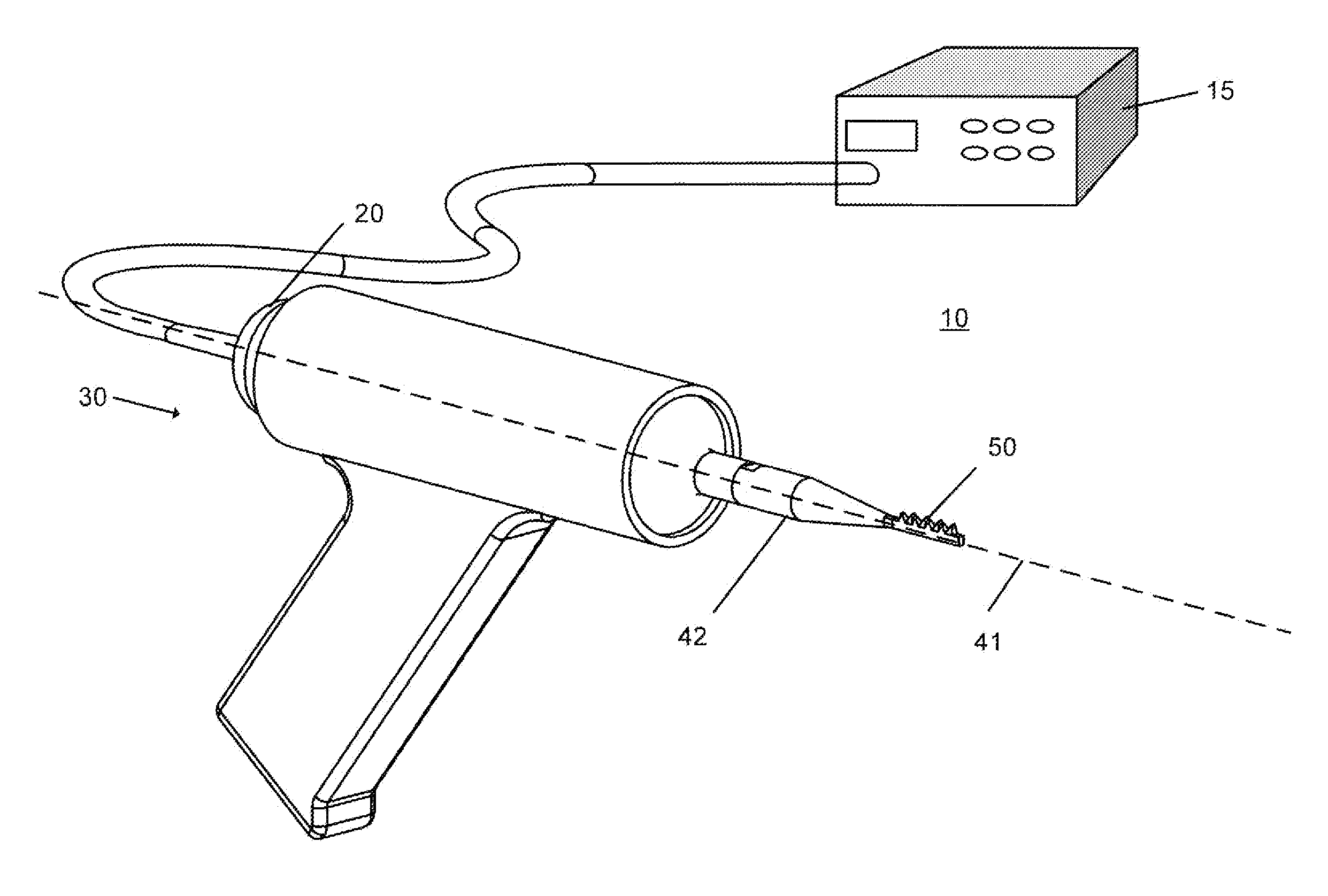
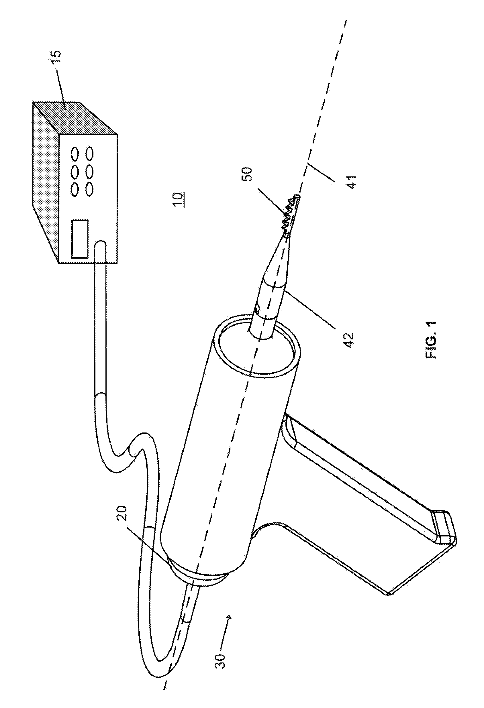
[0041]The present invention is an ultrasound medical method and device for use during surgical procedures. Several embodiments and details of the invention are shown in FIGS. 1-15 and described herein. The disclosure describes the apparatus and methods in reference to surgical procedures on bones, however the invention is appropriate for other surgical procedures generally.

[0042]FIG. 1 depicts one possible embodiment of the ultrasound apparatus 10 of the present invention. The depicted embodiment comprises an ultrasound generator 15 with an electrical cord supplying the ultrasound generator 15 its power, such as standard AC or battery power. The ultrasound generator 15 is in electrical communication with an ultrasound transducer 20 through a signal connector. A power switch may be provided to activate the ultrasound apparatus 10. The switch, for example, may be foot activated or a trigger or button located on the handpiece or generator.

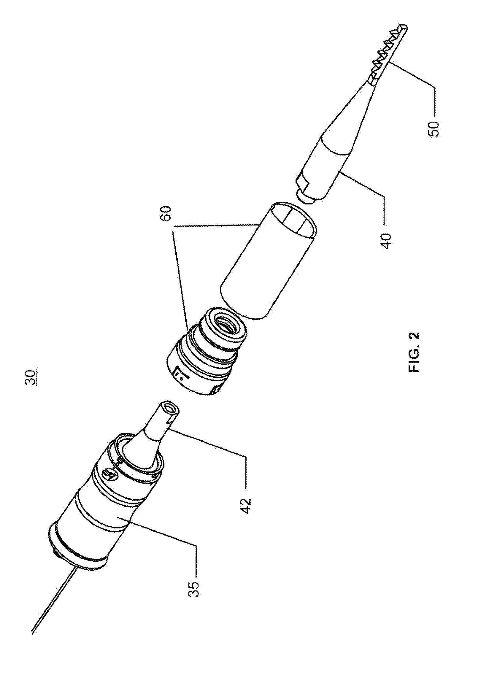
[0043]As shown by example in FIGS. 1 and 2, the...


PUM


Abstract

This invention discloses methods and devices using ultrasound energy for resecting bone tissue during surgical procedures. The disclosure describes the use of ultrasound surgical saw consisting of an ultrasound generator, ultrasound transducer and ultrasound horn including a cutting blade to resect bone tissue without excessive temperature rise during typical surgical procedures. The cutting blade provides a self-clearing design that includes at least two teeth disposed to prevent accumulation of bone chips within the proximity of the teeth. The design of the cutting blade allows the mechanical motion of the blade and the emission of the ultrasound energy to remove accumulated bone chips and prevent excessive temperature rise.

Description

BACKGROUND OF THE INVENTION[0001]The following invention relates generally to instrumentalities for cutting bone during surgery. More particularly, the instant invention is directed to a high speed surgical saw which uses a drive mechanism to move a cutting blade back and forth at a high frequency. The drive mechanism is needed to impart a back and forth motion to the cutting blade and may be, for example, a reciprocating, semi-oscillating or ultrasound drive. In the preferred embodiment, described in detail herein, a ultrasound transducer is utilized as part of the drive mechanism for the surgical saw blade with a self-cleaning design. The surgical saw. blade may have a distal portion having at least one pair of teeth configured to be adjacent to each other and each of the pair of teeth having a cutting edge which is oriented with the teeth so that the cutting edge is disposed away from a centrally positioned longitudinal axis between the teeth. A gullet is then formed between the ...

Claims


Application Information

Patent Timeline
26 May 2011
Publication
US20110125174A1
IPC
A61B17/32
CPC
A61B17/14; A61B17/141; A61B17/148; A61B2017/320076; A61B17/320068; A61B17/144; A61B17/142; A61B2017/320078
Inventors
BABAEV, EILAZ