
Energy conservation systems and methods

Active Publication Date: 2011-05-26
FUEL SAVING TECH
View PDF36 Cites 19 Cited by
  • Summary
  • Abstract
  • Description
  • Claims
  • Application Information

AI Technical Summary

Benefits of technology

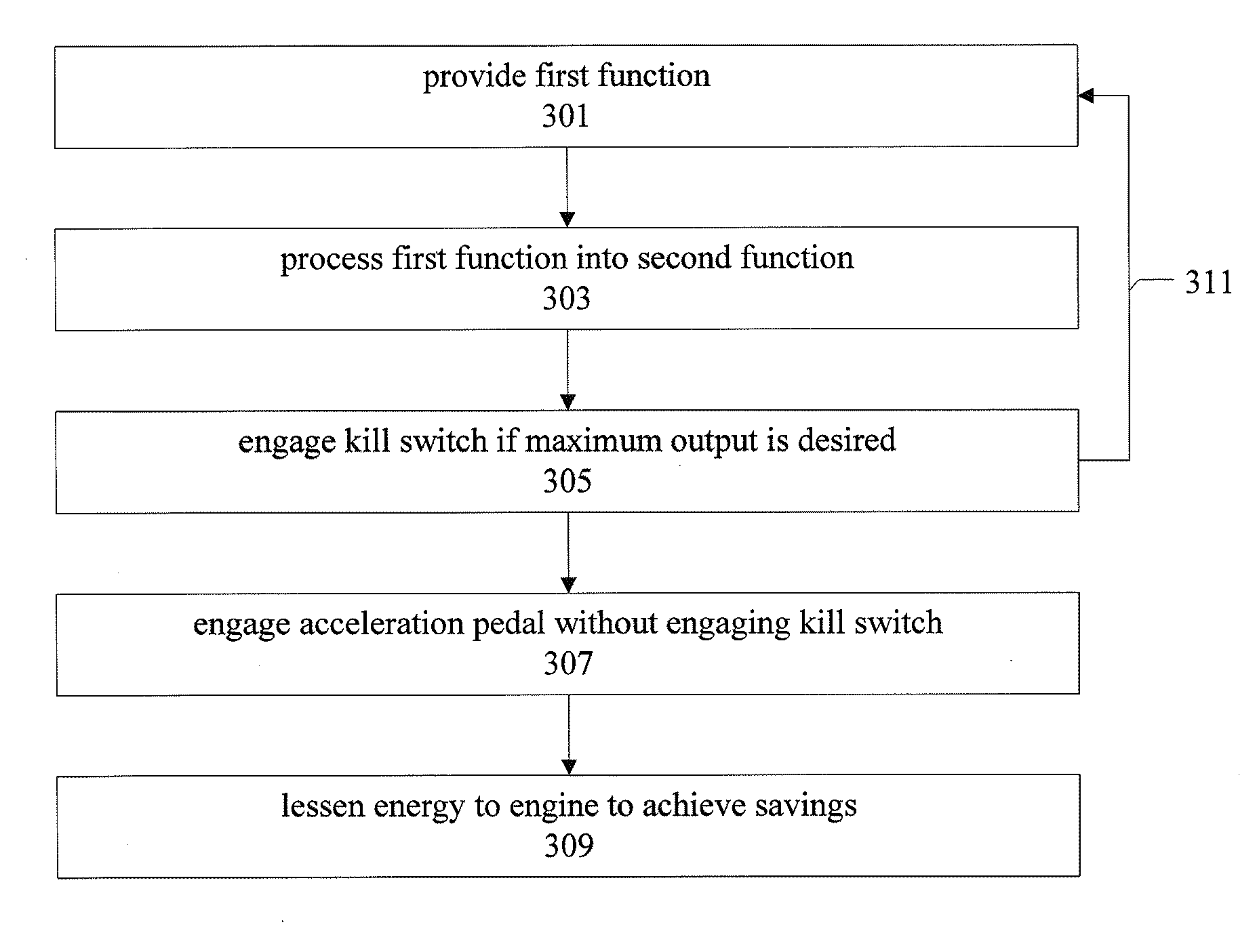
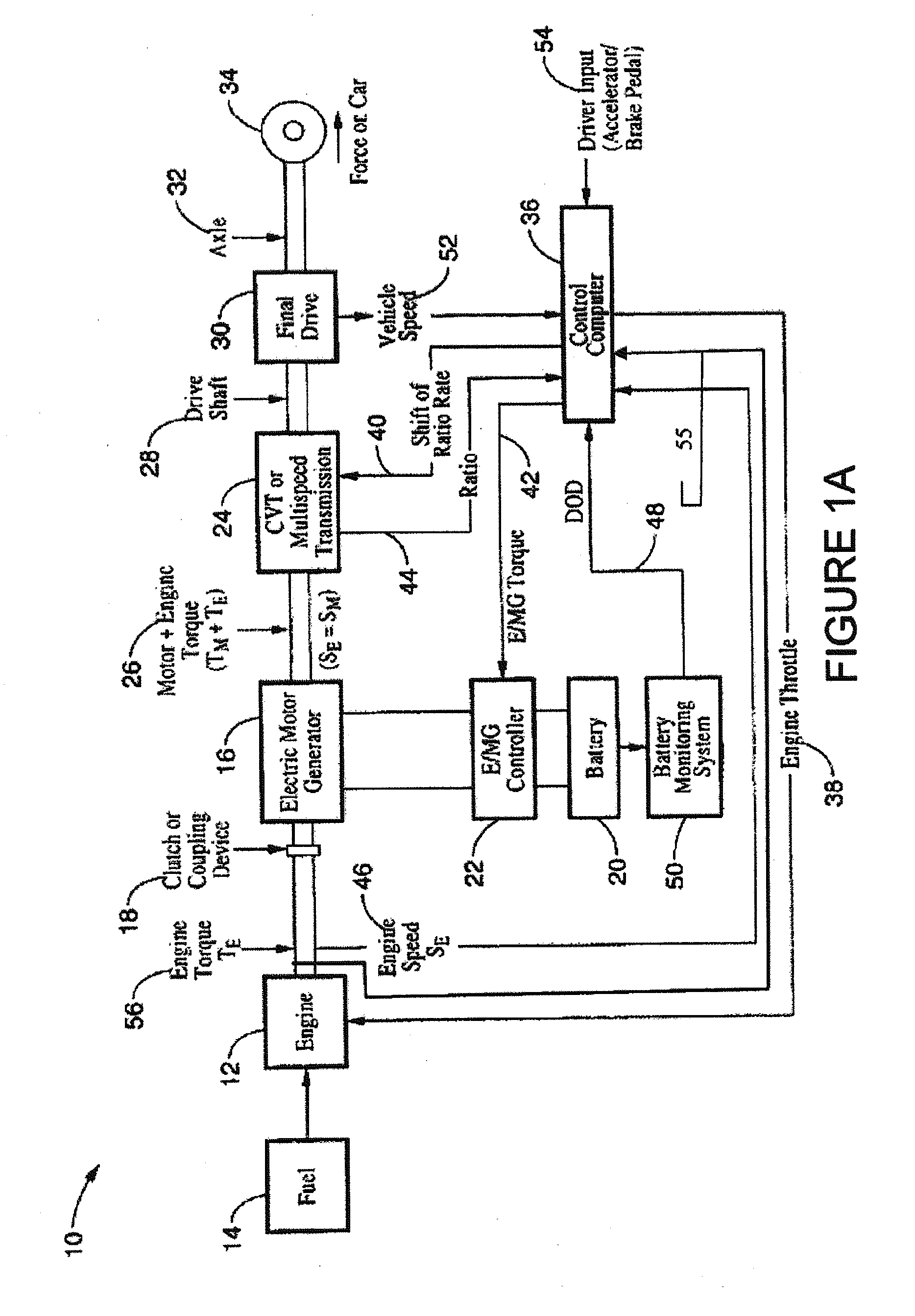
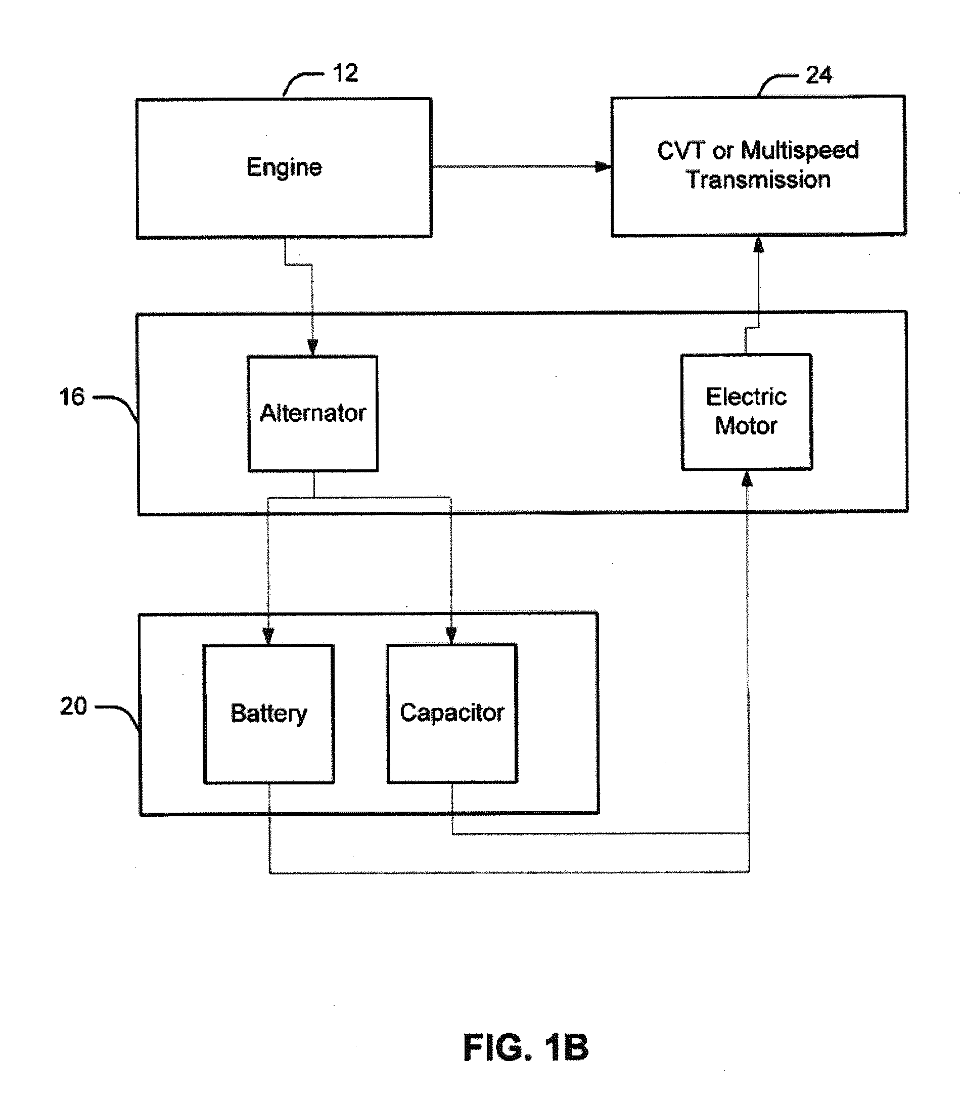
[0005]In accordance with certain embodiments, an energy conservation system and method for devices or energy consuming devices is provided. In some embodiments, the energy may comprise fuel. In some embodiments, the device or energy consuming device may comprise an engine such as an internal combustion engine. In certain embodiments the energy conservation system and method may apply to a cruise control module, a programmable logic controller, and / or a device control unit. Certain embodiments may dampen and / or cut energy delivery to a device or an energy consuming device. In certain embodiments an electric motor may substantially maintain a horsepower or torque output of an internal combustion engine when reducing, moderating, tapering, oscillating, cycling, cutting and / or dampening energy delivery to a device or an energy consuming device. Certain embodiments may be selectively tunable, and may include a feedback loop to display information relative to the possibility of and / or achievement of energy savings. Certain embodiments of the inventions may include a user-selectable override, causing the device or energy consuming device to make available, on demand from a user, the greatest amount of output power possible from the device.
[0015]According to certain embodiments, the method comprises displaying to a user an indication of a possibility or achievement of energy savings by the device if the device outputs work according to the second work output. In some embodiments, the method comprises supplementing an output of the device with output generated by a generator while the device outputs work according to the second work output. In some embodiments, the method comprises supplementing a work output of the device with work from a second device different from the device while the device outputs work according to the second work output. In some embodiments, the method comprises processing the second function for smoothness.

Problems solved by technology

Certain embodiments may dampen and / or cut energy delivery to a device or an energy consuming device.

Method used


Image

  • Energy conservation systems and methods
  • Energy conservation systems and methods
  • Energy conservation systems and methods

Examples


Embodiment Construction

[0046]The following description of illustrative non-limiting embodiments discloses specific configurations and components. However, the embodiments are merely examples of the present inventions, and thus, the specific features described below are merely used to describe such embodiments to provide an overall understanding of the inventions. One skilled in the art readily recognizes that the present inventions are not limited to the specific embodiments described below. Furthermore, certain descriptions of various configurations and components of the present inventions that are known to one skilled in the art are omitted for the sake of clarity and brevity. Further, while the term “embodiment” may be used to describe certain aspects of the inventions, the term “embodiment” should not be construed to mean that those aspects discussed apply merely to that embodiment, but that all aspects or some aspects of the disclosed inventions may apply to all embodiments, or some embodiments.

[0047...


PUM


Abstract

Methods and systems are described for conserving energy used by an energy consuming device. In certain embodiments, an energy conservation system can be configured to deliver energy to the energy consuming device for a period, followed by a period where energy delivery is dampened and / or cut. By cycling the delivery of energy in this fashion, the energy conservation can achieve a pulsed efficiency.

Description

CROSS-REFERENCES TO RELATED APPLICATIONS[0001]This application claims the benefit of U.S. Provisional Patent Application Ser. No. 61 / 292,823, entitled “Energy Conservation Systems and Methods,” filed on Jan. 6, 1010; this application is also a continuation-in-part application of U.S. patent application Ser. No. 12 / 497,507, entitled “Fuel Conservation Systems and Methods,” filed on Jul. 2, 2009, which claims the benefit of U.S. Provisional Patent Application Ser. No. 61 / 078,281, entitled “Fuel Conservation Systems and Methods,” filed on Jul. 3, 2008; all of the foregoing priority applications are hereby incorporated by reference in their entirety for all purposes.FIELD OF THE INVENTION[0002]Embodiments of the inventions generally relate to energy-consuming devices and energy conservation systems and methods.BACKGROUND OF THE INVENTION[0003]Energy, whether it be electricity, fossil fuels, or the like, allow for production and delivery of food and products worldwide. From cargo ships t...

Claims


Application Information

Patent Timeline
IPC IPC(8): G05B13/02
CPCB60K6/48B60W10/06B60W10/08B60W20/00B60W30/1882B60W2540/10B60K6/42Y02T10/6221Y02T10/6278Y02T10/6286B60K6/28B60Y2400/114B60W2710/0616F02D41/3011B60W20/13Y02T10/62
Inventor YU, JEFFREY N.HILL, JAMES W.DAVIS, GREGORY W.
Owner FUEL SAVING TECH
Learn More