Exhalation Valve Assembly

a technology of exhalation valve and assembly, which is applied in the direction of valve operating means/release devices, functional valve types, liquid transfer devices, etc., can solve the problems of difficult environment for the ventilator circuit and particularly the expiratory limb that handles the patient's exhalation gas

Inactive Publication Date: 2011-06-02
TYCO HEALTHCARE GRP LP
View PDF102 Cites 180 Cited by
  • Summary
  • Abstract
  • Description
  • Claims
  • Application Information

AI Technical Summary

Problems solved by technology

However, the ventilator circuit and particularly the expiratory limb that handles the patient's exhaled gas is a challenging environment.

Method used


Image

  • Exhalation Valve Assembly
  • Exhalation Valve Assembly
  • Exhalation Valve Assembly

Examples


Embodiment Construction

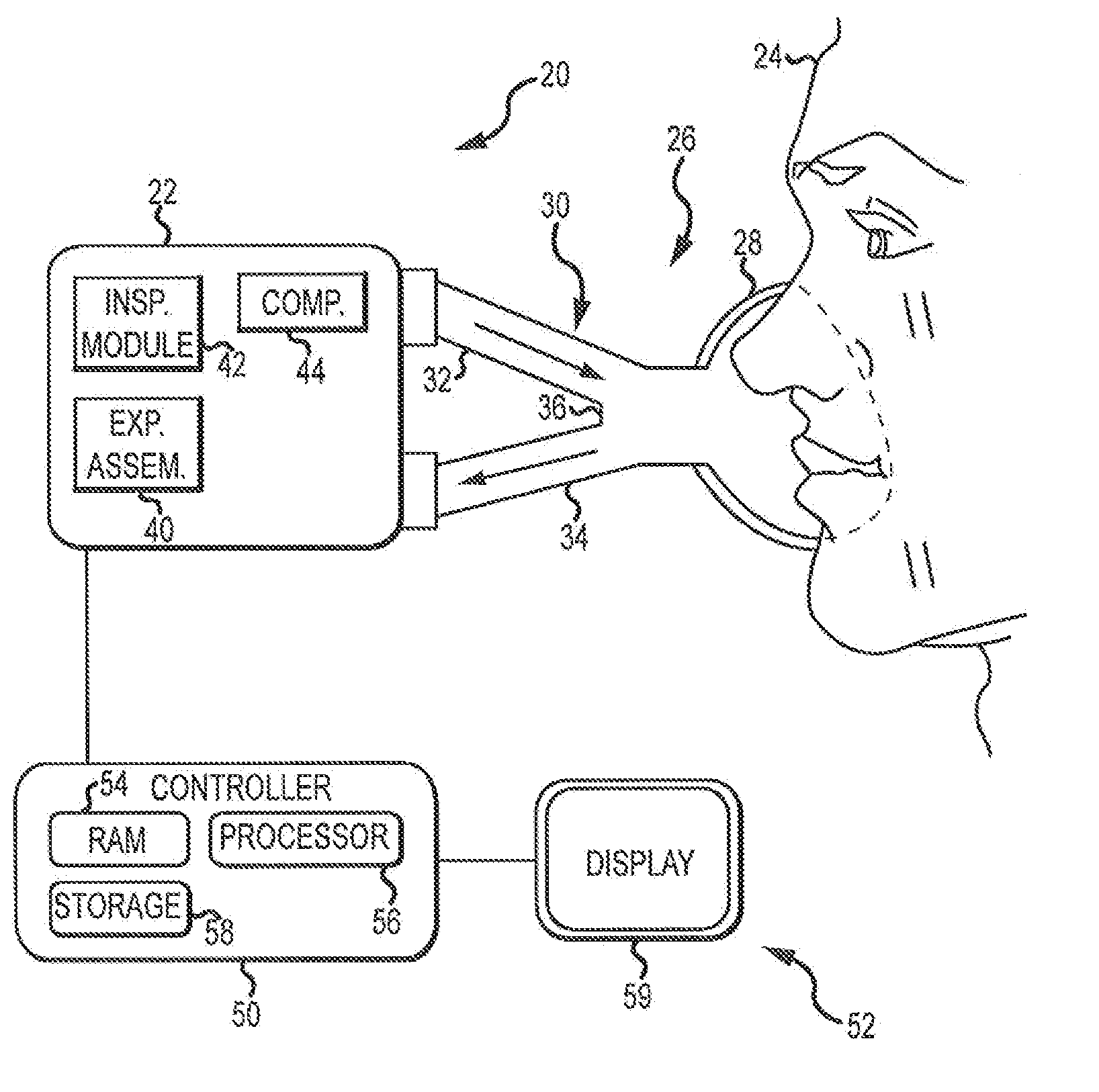
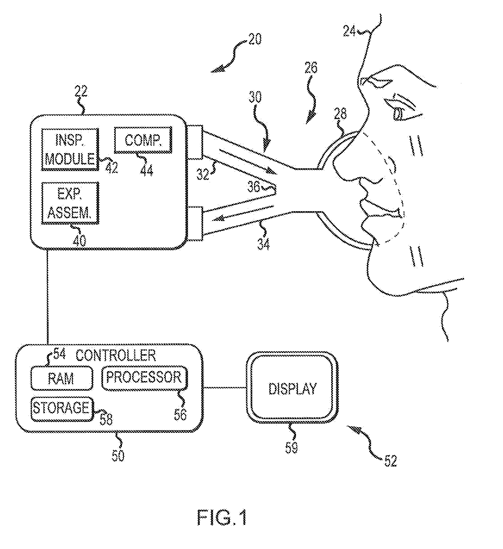
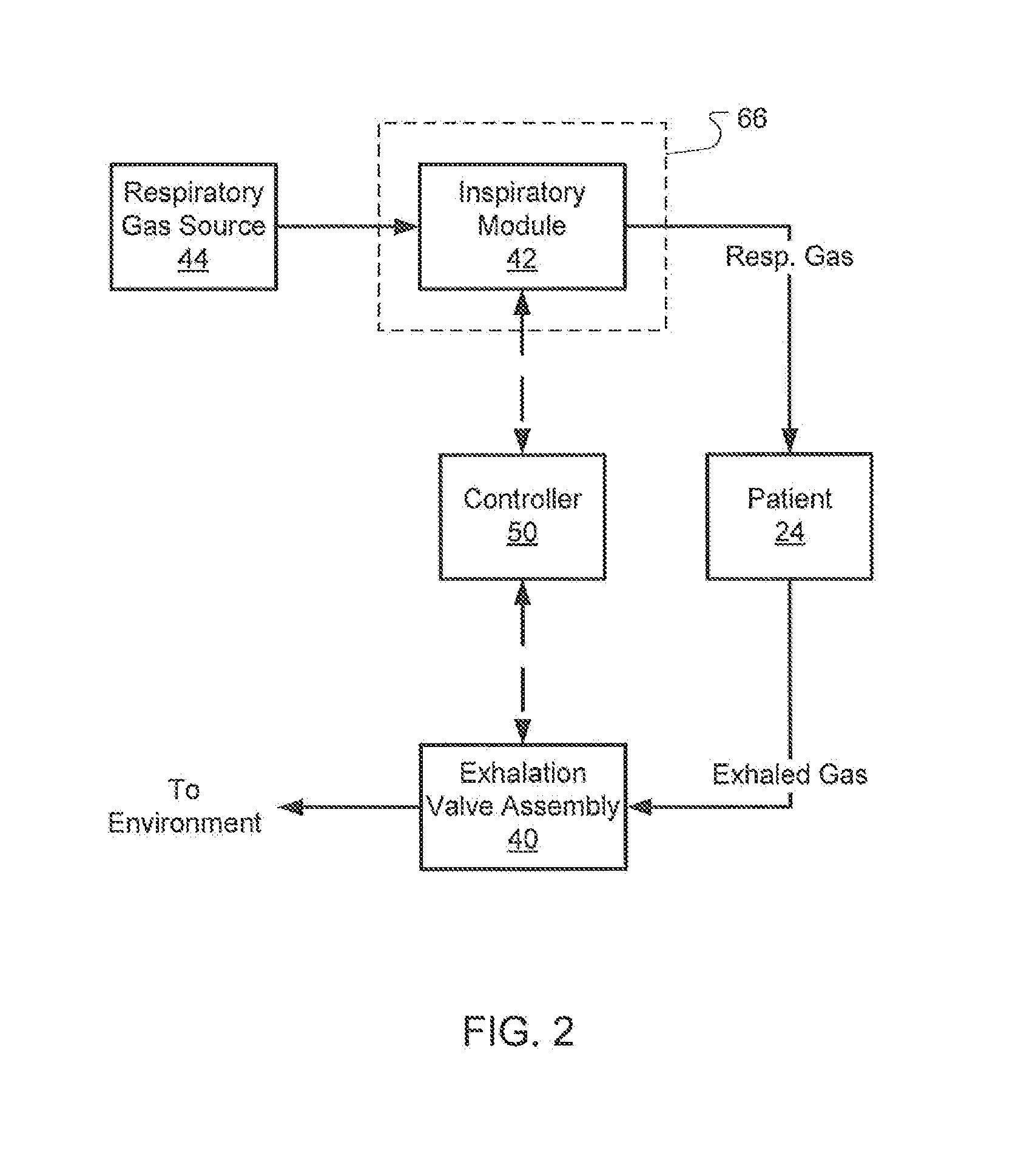
[0020]This disclosure describes embodiments of exhalation valve assemblies for use in ventilators. An exhalation valve assembly controls the pressure in the ventilator patient circuit via releasing exhaled gas from the circuit. In addition, the designs are described herein that improve the serviceability of the valve assembly, the capture of exhaled liquid and the filtration of the exhaled gas. In part, this is achieved by providing a separate actuator module and a removable valve module designed to control the pressure in the ventilator circuit so that exhaled gas contacts only the removable valve module. Depending on the embodiment, a removable filter / trap module may also be provided that includes a filter and condensate trap.

[0021]Although the techniques introduced above and discussed in detail below may be implemented for a variety of medical devices, the present disclosure will discuss the implementation of these techniques in the context of a medical ventilator for use in prov...


PUM


Abstract

An exhalation valve assembly that controls the pressure of exhaled gas in a ventilation system is described. The exhalation valve assembly includes an actuator module that may be fixed to the ventilation system and a valve module, removable for cleaning or disposal, through which the exhaled gas flows and that controls the pressure and release of the exhaled gas to the environment. Other components may also be incorporated into the assembly including a filter module, a flow meter and a condensate trap.

Description

RELATED APPLICATIONS[0001]This application is related to co-owned U.S. patent application Ser. Nos. ______; ______; ______; and ______ all filed ______, the entire disclosures of all of which are hereby incorporated herein by reference.INTRODUCTION[0002]Medical ventilators are designed to control the delivery of respiratory gas to a patient to supplement the patient's breathing efforts or to cause the inflation and deflation of a non-breathing patient's lung. Ventilators are often used in conjunction with a dual-limb patient circuit that conveys respiratory gas to a patient through a first tube referred to as the inspiratory limb and return exhaled gas from the patient through a second tube referred to as the expiratory limb.[0003]In order to accurately control the delivery of respiratory gas, pressure in the patient circuit is controlled so that gas is released during an exhalation phase and, typically but not always, flow is completely blocked during an inhalation phase. However, ...

Claims


Application Information

Patent Timeline
Patent Type & Authority Applications(United States)
IPC IPC(8): A61M16/20G05D7/06
CPCA61M16/00A61M16/0808A61M16/20A61M16/206A61M2016/0036A61M2205/502A61M16/205A61M2016/0021A61M16/0063A61M16/1065A61M16/0858Y10T137/86002Y10T137/86027Y10T137/0396A61M16/024A61M16/0833
Inventor WINTER, DAVID PHILLIPSANBORN, WARREN G.
Owner TYCO HEALTHCARE GRP LP
Why Eureka
Try Eureka