Apparatus for simultaneously dispensing two products

Inactive Publication Date: 2011-06-02
WORLD WIDE PACKAGING
View PDF25 Cites 1 Cited by
  • Summary
  • Abstract
  • Description
  • Claims
  • Application Information

AI Technical Summary

Benefits of technology

[0011]Embodiments of the present invention comprise an inner channel and an outer channel to facilitating the movement of the products within the product dispensing unit and allows for both products to be dispensed from the product dispensing unit at a dispensing site on the nozzle of the outer tube. According to an embodiment of the present invention, the outer channel provides for fluid communication between the outer tube cavity and the dispensing site of the nozzle of the outer tube. The inner channel provides for fluid communication between the inner tube cavity and the dispensing site of the nozzle of the outer tube. As a result, the product in the outer tube may flow through the outer channel and the product in the inner tube may flow through the inner channel. Both products are dispensed from the product dispensing unit at the nozzle of the outer tube.
[0012]The inner tube is primarily secured to the outer tube by way of an interaction between the nozzle of the outer tube and the inner tube first end. According to an embodiment of the present invention, the inner tube first end includes an engagement member and a dispensing point. The engagement member may provide the interaction to secure the inner tube to the outer tube. The engagement member may be a circular portion of the inner, tube first end that creates a secure fri

Problems solved by technology

However, conventional product dispensing units having a nested arrangement fail to provide a secure fit between the inner tube and the outer tube.
Without a secure fit between the two tubes, there is a high likelihood that the inner tube will decouple from the outer tube, thereby interrupting the flow of the products through the product dispensing unit.
In addition, insufficiently securing an inner to with an outer tube may result in seepage of products between tubes and issues confronted when filling and sealing the product dispensing unit.
The ribs provide the only means of engagement and as a result the inner tube lacks sufficient engagement with the outer tube.
As with other conventional product dispensing units, these small ribs provide an insufficient means of securing the inner tube to the

Method used


Image

  • Apparatus for simultaneously dispensing two products
  • Apparatus for simultaneously dispensing two products
  • Apparatus for simultaneously dispensing two products

Examples


Example

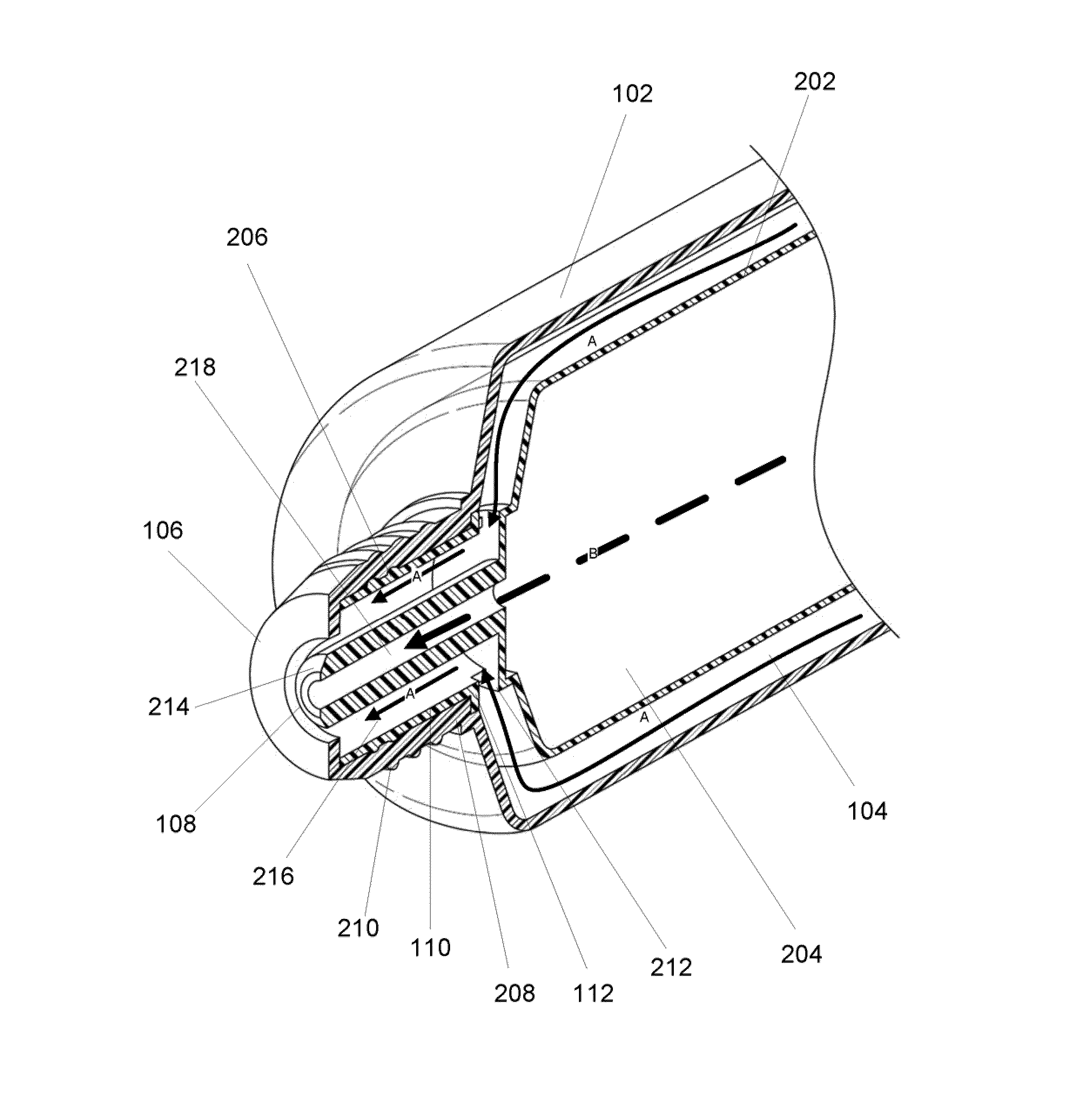
[0020]The present invention relates to a product dispensing unit configured to separately house two products and simultaneously dispense both products in response to the application of pressure to the product dispensing unit. The product dispensing unit comprises an outer tube substantially surrounding an inner tube. The outer tube is configured to house a first product and the inner tube is configured to house a second product.

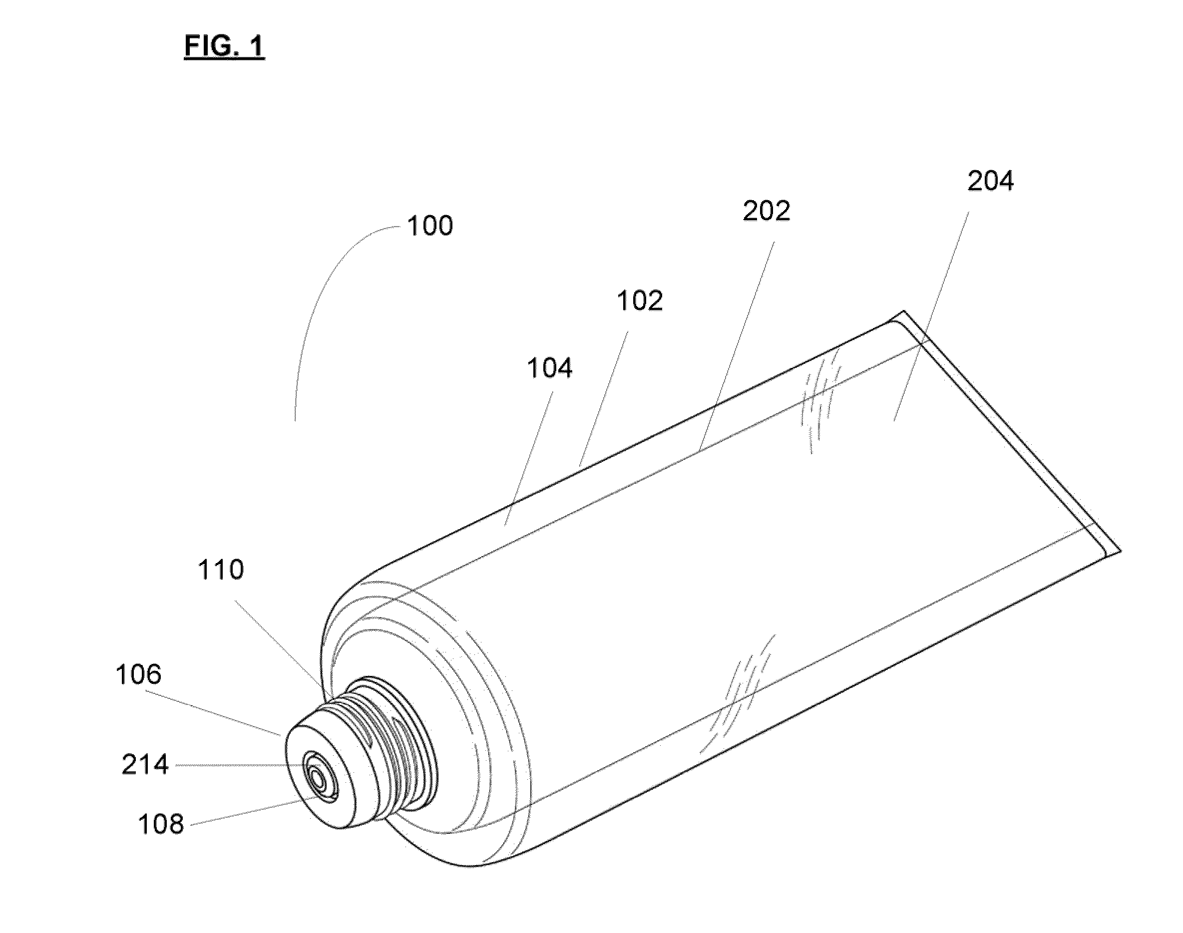
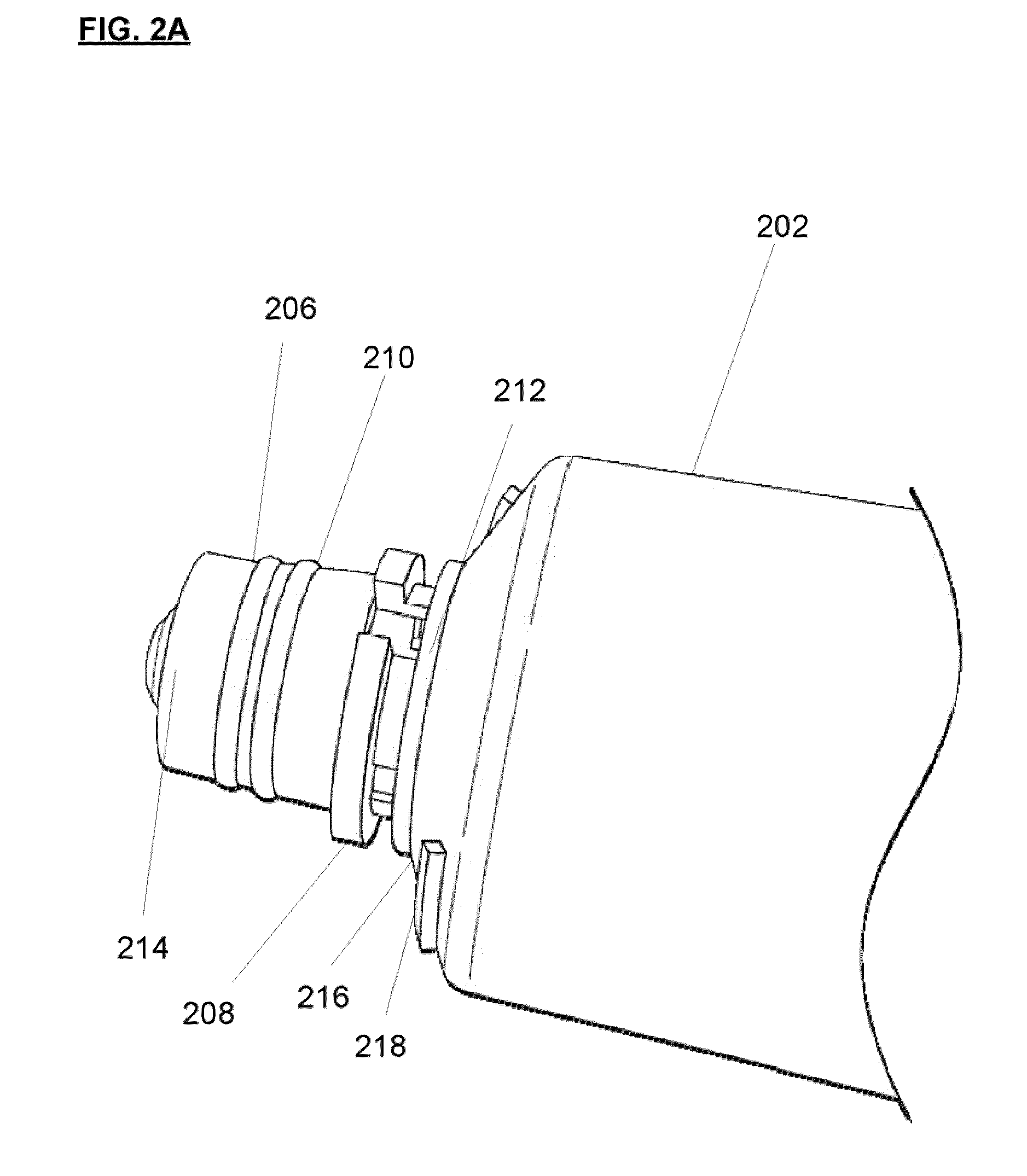
[0021]FIG. 1 depicts an exemplary product dispensing unit 100 according to an embodiment of the present invention. Product dispensing unit 100 comprises an outer tube 102 and an inner tube 202. The outer tube 102 comprises an outer tube cavity 104 configured to substantially surround the inner tube 202 as well as house a first product (not shown). The inner tube 202 is secured to the outer tube 102 and comprises an inner tube cavity 204. The inner tube cavity 204 is configured to house a second product (not shown). Portions of the inner tube 202 are illustrat...


PUM


Abstract

A product dispensing unit is provided configured to house two products in separate tubes, wherein the two products may be simultaneously dispensed from the product dispensing unit. According to an embodiment of the present invention, the product dispensing unit comprises an outer channel configured to facilitate the flow of the first product flows from an outer tube cavity to a dispensing site and an inner channel configured to facilitate the flow of a second product from an inner tube cavity to dispensing site. Application of pressure to the product dispensing unit may results in simultaneously dispensing the first product and the second product from the product dispensing unit.

Description

FIELD OF THE INVENTION[0001]The present invention relates to an apparatus for dispensing products, more particularly, to an apparatus configured to house two products, wherein the products remain separated while housed in the apparatus, and may be simultaneously dispensed from the apparatus.BACKGROUND OF THE INVENTION[0002]Product dispensing units are known in the art to allow for housing and dispensing of fluid products. As used herein, the term “product” is intended to include, but is not limited to, any fluid substance or material capable of flowing, including for example, gels, creams, cosmetics, therapeutic remedies, medicines, and food items. Most product dispensing units provide a reservoir for housing a single product and an outlet where the product is dispensed. A user may apply pressure to an external portion of the product dispensing unit to dispense the contained product from the unit.[0003]In addition to product dispensing units configured to house and dispense a single...

Claims


Application Information

Patent Timeline
IPC IPC(8): B67D7/74
CPCB65D35/22B65D81/3244B65D35/242
Inventor HAYET, JEFFREY MARCWIGHTMAN, JAMES C.
Owner WORLD WIDE PACKAGING
Why Eureka
Try Eureka